Introduction
Every post in this cluster has been building toward this moment. Post #4 sized the array. Post #5 configured the strings. Post #6 established the specifications that determine real-world controller performance. This post applies all of it to a single complete worked example: MPPT controller sizing for a 48V lithium system with a 2,400W array in a coastal West African installation, verified against real datasheet values for a specific controller model from first constraint to final sign-off.
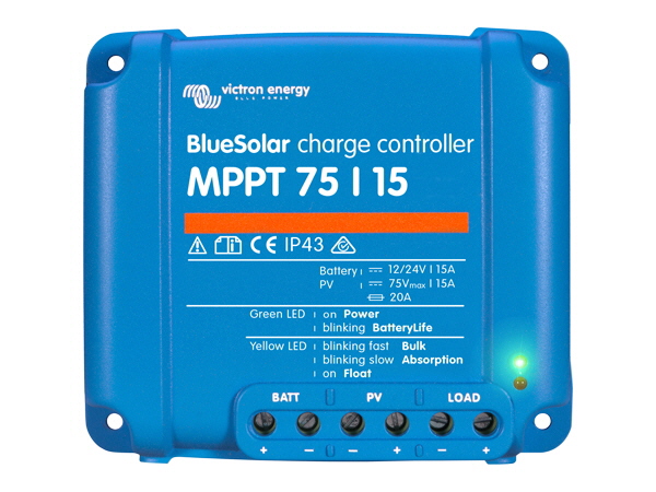
The candidate controller for this worked example is the Victron Energy SmartSolar MPPT 150/60. I am using this model not as a product endorsement but because it is a well-documented controller with publicly available datasheet specifications that allow every claim in this post to be independently verified. Every check in the four-constraint selection framework will be performed against its published values. Where the controller passes, I will show the margin. Where a different controller would fail, I will show exactly why.
If you have come to this post looking for a controller recommendation for a specific system, the framework you need is here. How to size a solar charge controller for a 2,400W array on a 48V system is not a question with a single answer. It is a constraint satisfaction exercise with four verification steps, and passing all four is what defines a correct selection. The rest of this post works through each one.
The Four-Constraint Selection Framework
Before running any numbers, I want to establish the complete set of constraints the controller selection must satisfy, because the order in which they are applied matters. Each constraint narrows the field of acceptable controllers, and applying them in the correct sequence avoids the common mistake of selecting a controller that passes the most visible check while failing a less obvious one.
The four constraints are output current capacity, input voltage window compliance, input power and oversizing ratio, and thermal environment compatibility. A controller that satisfies three and fails one is not a marginally acceptable selection. It is a wrong selection that will either clip production, damage itself, or underperform in a predictable and avoidable way.
The system parameters for this worked example are drawn directly from the calculations developed across Posts #4, #5, and #6 and are summarized here as the reference inputs for every check that follows:
| Parameter | Value |
| Daily energy demand | 4,916Wh |
| Array STC rating | 2,400W (6 x 400W panels) |
| String configuration | 3S2P — two strings of 3 panels in series |
| Panel Voc_STC | 41V per panel |
| Panel Vmp_STC | 34V per panel |
| Panel Voc temp coefficient | -0.29%/°C |
| Panel Vmp temp coefficient | -0.34%/°C |
| Derating factor | 0.718 (tropical installation) |
| Battery system voltage | 48V LiFePO4 |
| Minimum site temperature | 18°C |
| Maximum cell temperature | 70°C |
| Installation location | Coastal West Africa (~6°N latitude) |
The selection sequence I apply is output current first, because it establishes the controller’s fundamental capacity and rules out underpowered models immediately. Input voltage window second, because it rules out controllers whose specifications are incompatible with the string configuration. Input power and oversizing ratio third, because it confirms the array-to-controller power relationship is within productive bounds. Thermal environment fourth, because it applies the real-world operating conditions that determine whether the controller can actually deliver its rated performance at this specific site.
For the derivation of the system parameters used in this post, refer to our engineering guides on how to size a solar array for an off-grid lithium battery system, series vs parallel vs series-parallel solar array wiring, and how MPPT charge controllers work and how to select the right one.
Step 1: Calculating Required Output Current
The output current calculation is the first and most important sizing step because it establishes the minimum controller capacity the system requires. Every other constraint operates within the boundary this number sets. Getting it wrong in either direction, undersizing or oversizing beyond what thermal margin and expansion plans justify, produces a selection that either limits system performance or wastes capital.
The governing equation is:
I_out_required = (P_array_STC x Derating Factor) / V_battery
Where:
I_out_required  = minimum required controller output current (A)
P_array_STC = total array STC rated power (W)
Derating Factor = real-world array output fraction
V_battery = nominal battery system voltage (V)

Applying the worked system parameters:

I_out_required = (2,400W x 0.718) / 48V
I_out_required = 1,723W / 48V
I_out_required = 35.9A
The Victron SmartSolar MPPT 150/60 is rated at 60A maximum output current at 48V system voltage. Against the 35.9A requirement, this gives a margin of 24.1A, or 67 percent above the minimum required. That margin is not waste. It serves three distinct purposes that become visible only when the system is operating under real conditions.
The first purpose is thermal headroom. As Section 5 will show, the controller’s output current derates above 40 degrees Celsius ambient. A controller selected at exactly the required output current with no margin will begin clipping production as soon as the enclosure temperature rises above the derating threshold, which in a tropical installation is a daily occurrence. The second purpose is battery voltage sag. As a LiFePO4 battery discharges, its terminal voltage drops from approximately 53V at full charge to 44V at 20 percent state of charge. Because output power equals output current multiplied by battery voltage, a lower battery voltage at the same output power requires a higher output current from the controller.
A controller sized to the nominal 48V output current with no margin will clip production during the hours when the battery is in its lower state of charge and irradiance is simultaneously high. The third purpose is future array expansion. A 60A controller on a system that currently requires 35.9A can accommodate an array expansion to approximately 4,000W STC before the output current becomes the binding constraint.
The practical rule for MPPT controller sizing for 48V lithium systems is to calculate the required output current as shown, then select a controller rated at a minimum of 110 to 115 percent of that figure, with 125 to 130 percent preferred on tropical installations where thermal derating is a daily operating condition rather than an occasional event.
Step 2: Input Voltage Window Compliance
The input voltage window check is where string configuration and controller selection intersect, and it is the check that most commonly reveals an incompatibility between a string design and a candidate controller. The Victron SmartSolar MPPT 150/60 has a maximum input voltage of 150V and an MPPT operating range of 70V to 145V. Both limits must be verified against the string’s voltage behavior across the full temperature range the site will experience.
The cold Voc check establishes the maximum voltage the controller’s input stage will ever see. Using the 3S string parameters from Posts #4 and #5:
Voc_cold = N_series x Voc_STC x (1 + Voc_coeff x (T_min – 25))
Voc_cold = 3 x 41V x (1 + (-0.0029) x (18 - 25))
Voc_cold = 123V x (1 + 0.0203)
Voc_cold = 123V x 1.0203 = 125.5V
Requirement: Voc_cold < 150V x 0.90 = 135V
Result: 125.5V < 135V  ->  PASS  (7% below safety threshold)
The hot Vmp check establishes the minimum operating voltage the string delivers to the controller during peak afternoon conditions. This is the check most commonly skipped, and it is the one that produces a silent, chronic production loss when it fails:
Vmp_hot = N_series x Vmp_STC x (1 + Vmp_coeff x (T_cell_max – 25))
Vmp_hot = 3 x 34V x (1 + (-0.0034) x (70 - 25))
Vmp_hot = 102V x (1 - 0.153)
Vmp_hot = 102V x 0.847 = 86.4V

Requirement: Vmp_hot > 70V x 1.10 = 77V
Result: 86.4V > 77V  ->  PASS  (12% above minimum threshold)
Both checks pass for the Victron SmartSolar 150/60 with this 3S string configuration. Now consider what happens with a controller that has a maximum input voltage of 100V, a specification common on lower-cost controllers in this current rating class. Applying the cold Voc check:
Requirement: Voc_cold < 100V x 0.90 = 90V
Result: 125.5V > 90V ->  FAIL
Cold Voc exceeds safety threshold by 39.4%
Connecting this string to a 100V controller = input stage overvoltage damage
The 125.5V cold Voc of this string exceeds the safety threshold of a 100V controller by 39.4 percent. The solution is not to redesign the string. The solution is to select a controller with a maximum input voltage that accommodates the string’s cold Voc with the required safety margin. The Victron SmartSolar 150/60’s 150V maximum input handles this string safely. A 100V controller does not, regardless of how well it satisfies the output current requirement. This is exactly the field failure mode described in Section 9: buying a controller with the correct output current rating but the wrong maximum input voltage for the string configuration it will be connected to.
Step 3: Input Power and Oversizing Ratio
With output current and input voltage window both verified, the third constraint to check is the relationship between the array’s STC rated power and the controller’s effective input power capacity. The Victron SmartSolar MPPT 150/60 at 48V system voltage has a maximum output power of 60A multiplied by 48V, which gives 2,880W. The array STC rating is 2,400W. The oversizing ratio is:
Oversizing Ratio = P_array_STC / P_controller_output_rated
Oversizing Ratio = 2,400W / 2,880W = 0.83
An oversizing ratio of 0.83 means the array is slightly undersized relative to the controller’s maximum output capacity. There is no clipping at any irradiance level because the array can never exceed the controller’s rated output at this system voltage. Every watt the array produces under real operating conditions reaches the battery without restriction.
The question the oversizing ratio analysis should also address is whether a deliberate oversizing strategy would be beneficial on this installation. Intentional oversizing allows the controller to reach its rated output sooner after sunrise and maintain it longer into the evening, harvesting more energy during the shoulder hours of the day at the cost of clipping some midday peak production. The economic case for this strategy depends critically on the irradiance profile of the installation site.
In high-irradiance tropical locations like coastal West Africa, peak midday irradiance regularly reaches 900 to 1,000W/m2 for extended periods. At these irradiance levels, a deliberately oversized array would be clipped for several hours each clear day, losing exactly the high-value production that the oversizing was intended to recover.
The clipping energy integral, the area under the irradiance curve that exceeds what the controller can process, is large in high-irradiance climates and small in persistently cloudy or temperate climates. For this reason, the productive oversizing range of 1.0 to 1.30 has a lower practical break-even in tropical installations than in northern European or highland African climates where peak irradiance rarely sustains above 700 to 800W/m2 for extended periods. On this coastal West African installation, the 0.83 ratio is appropriate.
Step 4: Thermal Environment Assessment
The thermal assessment is the constraint that converts a controller selection that looks correct on a datasheet into one that is verified for the specific installation environment. The Victron SmartSolar MPPT 150/60 is rated at 60A full output at 25 degrees Celsius ambient. In a coastal West African installation, the controller will never operate at 25 degrees Celsius ambient during peak production hours. The question is how much output current it actually delivers under real thermal conditions, and whether that derated figure still covers the 35.9A requirement.
The thermal chain for this installation runs as follows. The peak ambient air temperature at the installation site is approximately 32 degrees Celsius during the hottest months. A controller installed in an enclosure that is not actively ventilated will experience an internal temperature rise above ambient due to the heat generated by its own conversion losses and the heat accumulated in the enclosure from the surrounding environment. For a standard wall-mounted electrical enclosure with no forced ventilation and moderate solar exposure on the enclosure surface, an internal temperature rise of 15 degrees Celsius above ambient is a realistic conservative estimate.
T_controller = T_ambient + T_enclosure_rise
T_controller = 32°C + 15°C = 47°C
The Victron SmartSolar MPPT 150/60 begins thermal derating at 40 degrees Celsius and reaches 50 percent of rated output at 60 degrees Celsius, giving a linear derating slope of 50 percent reduction over 20 degrees Celsius, or 2.5 percent per degree Celsius above the derating threshold. Applying this to the 47 degree Celsius operating temperature:
I_derated = I_rated x (1 - Derating Slope x (T_controller - T_threshold))
I_derated = 60A x (1 - 0.025 x (47 - 40))
I_derated = 60A x (1 - 0.175)
I_derated = 60A x 0.825 = 49.5A
At 47 degrees Celsius controller temperature, the Victron SmartSolar 150/60 delivers 49.5A rather than its rated 60A. Against the 35.9A system requirement, this leaves a margin of 13.6A, or 38 percent above the minimum required. The thermal derating at this installation does not compromise system performance.
The ventilation specification that eliminates the derating concern entirely is straightforward: a ventilated enclosure with a minimum of 50mm clearance on all sides, mounted in a shaded location away from direct solar radiation, with a louvred vent at the base and a protected vent at the top to promote natural convective airflow. Under these conditions the internal temperature rise above ambient drops to 5 to 8 degrees Celsius, giving a controller operating temperature of 37 to 40 degrees Celsius, which is at or below the derating threshold entirely.
Thermal Assessment Summary:
1. Ambient temperature -> 32°C (peak, hottest months)
2. Unventilated enclosure rise -> +15°C  ->  controller at 47°C
3. Derated output at 47°C -> 49.5A  vs  35.9A required  ->  PASS
4. Ventilated enclosure rise -> +5 to 8°C  ->  controller at 37 to 40°C
5. Derated output at 37 to 40°C -> 57 to 60A  ->  full or near-full rated output

Recommendation -> ventilated enclosure, shaded mounting location
Step 5: Charge Profile and LiFePO4 Compatibility
With the four hardware constraints verified, the fifth step shifts from sizing to configuration: confirming that the candidate controller can be programmed to charge the LiFePO4 battery correctly. A controller that passes every electrical and thermal check but cannot be configured with the correct charge parameters for the specific battery chemistry is still the wrong controller for a lithium system.
The Victron SmartSolar MPPT 150/60 supports fully user-configurable charge parameters through the VictronConnect application, available on iOS, Android, and PC via Bluetooth or USB interface. The absorption voltage is independently adjustable, which allows the setpoint to be matched to the specific battery manufacturer’s recommended absorption voltage rather than being locked to a preset chemistry profile. The float voltage is independently adjustable and can be set below the absorption voltage, which is the mandatory requirement for LiFePO4 to avoid continuous CV charging after the bulk phase completes. The absorption termination condition supports current-taper cutoff, meaning the absorption phase ends when charging current drops below a configurable threshold rather than running for a fixed time period. Equalization can be fully disabled.
For systems using Victron-compatible batteries that communicate via VE.Can, the charge parameters are additionally managed dynamically by the BMS through CVL and CCL signals, which override the programmed setpoints in real time. In this mode the programmed setpoints serve as a fallback ceiling rather than the active charge control, and the BMS takes direct responsibility for cell-level voltage management.
For systems using non-Victron batteries, the correct approach is to obtain the specific battery manufacturer’s recommended charge parameters, enter them manually into VictronConnect, and verify that the programmed values are within the BMS’s protection thresholds with adequate margin. The programmed absorption voltage should be at or below the BMS’s high voltage protection threshold, not above it, because the BMS protection layer is a last resort, not a design target.
For the full LiFePO4 charge parameter reference and the rationale behind each setpoint, refer to our detailed treatment in how MPPT charge controllers work and how to select the right one.
Step 6: BMS Communication Protocol Verification
The final configuration check before accepting the controller selection is communication protocol compatibility between the Victron SmartSolar MPPT 150/60 and the battery BMS. This check is model-specific and firmware-specific, not product-family-specific, and it is the one most commonly skipped because the incompatibility does not prevent the system from operating. It prevents the system from operating correctly under all conditions, which is a different and more insidious problem.

The Victron SmartSolar MPPT 150/60 supports Victron’s VE.Can protocol, which allows direct communication with Victron-branded batteries and with third-party batteries that implement the Victron-compatible CAN bus protocol. Pylontech batteries, which are widely used with Victron inverter systems in the West African market, communicate via a Pylontech CAN protocol that requires a VE.Can to CAN bus adapter cable to interface with the SmartSolar controller. The adapter is a published Victron accessory, but it must be explicitly specified and the firmware version of the SmartSolar must support the Pylontech protocol variant.
This is an example of the model versus product family distinction: the SmartSolar 150/60 supports VE.Can communication, but only on units with the correct communication port hardware, which is present on the standard model but absent on the utility or MPPT RS variants of the same controller family.
On systems where the BMS speaks only Modbus RTU over RS485 and the controller supports only VE.Can, the fallback position is fixed charge setpoints with conservatively configured voltage limits. In this configuration the programmed absorption voltage must be set low enough to protect the most voltage-sensitive cell group in the pack under worst-case imbalance conditions, not at the battery’s nominal maximum charge voltage. A conservative absorption setpoint of 3.55V per cell rather than 3.65V per cell on a LiFePO4 system provides a meaningful safety margin against cell-level overcharge when BMS communication is absent.
For a detailed treatment of how CVL and CCL signals protect cell integrity when BMS communication is active, and what the consequences are when it is not, refer to our engineering posts on CVL, CCL, and DCL dynamic battery limits in real-time systems and BMS-inverter communication protocols in modern solar systems.
Split Array Architecture: When One Controller Is Not Enough
The worked example in this post uses a 2,400W array that fits comfortably within the Victron SmartSolar MPPT 150/60’s capacity at 48V. There are two scenarios where a single controller of this type is not sufficient and the array must be split across two independent controllers: when the total array power requires an output current that exceeds the maximum rating of any single available controller model, and when the array has two sections with meaningfully different orientations, tilt angles, or shading profiles that would produce mismatch losses if combined at a single MPPT input.

The output current scenario is straightforward to evaluate. If the same system were scaled to a 4,800W array with the same 0.718 derating factor on a 48V system, the required output current would be:
I_out_required = (4,800W x 0.718) / 48V = 3,446W / 48V = 71.8A
No single standard MPPT controller in the Victron SmartSolar range rated for 48V systems exceeds 70A output current as a standalone unit. The correct solution is two Victron SmartSolar MPPT 150/60 controllers, each connected to one of the two 2,400W string groups, each independently tracking its own string, and each feeding the same 48V battery bank in parallel. This configuration delivers the full 71.8A combined output current to the battery with both controllers operating within their individual rated limits.
Paralleling two MPPT controllers on a shared battery bank is standard practice and works correctly because each controller regulates its own output current independently based on battery terminal voltage. The controllers do not interfere with each other because they are each controlling their own array input, not competing for the same source. What is not acceptable is connecting two controllers to the same string group in an attempt to share the input current, because the two controllers will run independent perturb-and-observe algorithms on the same source simultaneously, interfere with each other’s tracking cycles, and produce an unstable operating condition that delivers less energy than either controller would on its own.
On Victron systems where multiple SmartSolar controllers share a battery bank, the VE.Network synchronization feature allows the controllers to coordinate their charge state awareness so both units transition between bulk, absorption, and float phases together rather than independently, which prevents one controller from holding the battery at absorption voltage while the other has already moved to float.
The Complete Selection Summary and Field Failure Modes
Every constraint in the four-step selection framework has now been verified against the Victron SmartSolar MPPT 150/60 for this specific installation. The results are summarized in the table below, with the derivation source for each parameter referenced to the post where it was calculated.
| Parameter | Required / Calculated | Controller Spec | Result |
| Required output current | 35.9A | 60A rated | PASS — 67% margin |
| Cold Voc (3S, 18°C) | 125.5V | 150V max input | PASS — 7% below 135V |
| Hot Vmp (3S, 70°C cell) | 86.4V | 70V min MPPT | PASS — 12% above 77V |
| Oversizing ratio | 0.83 | N/A | PASS — no clipping |
| Derated output at 47°C | 35.9A required | 49.5A derated | PASS — 38% margin |
| Absorption voltage | User-configurable | VictronConnect: adjustable | PASS |
| Float voltage | Below absorption | Independently adjustable | PASS |
| Equalization | Disabled | Can be disabled | PASS |
| BMS communication | CAN bus / VE.Can | VE.Can + adapter | PASS — verify firmware |
Every constraint passes. The Victron SmartSolar MPPT 150/60 is a verified selection for this system under these conditions. The selection is not based on brand preference or market position. It is based on six documented checks against published specifications.
Common Controller Selection Failure Modes Observed in Field Systems:
1. Undersized output current — sizing to STC without applying derating factor
Consequence: clips production on every clear day
2. Ignoring cold Voc — using nominal string voltage without temperature correction
Consequence: input stage overvoltage damage on cold mornings
3. Buying 100V max input controller for 3S string in temperate or cold climates
Consequence: controller damage or nuisance overvoltage protection trips
4. Using preset lithium profile without verifying voltage thresholds
Consequence: systematic overcharge or chronic undercharge
5. Oversizing array beyond 1.30 ratio in high-irradiance tropical climates
Consequence: clipping losses exceed morning harvest benefit on clear days
6. Selecting correct product family but wrong model tier
Consequence: BMS communication absent, dynamic charge limiting unavailable
Conclusion
The four-constraint selection framework applied in this post is not specific to the Victron SmartSolar MPPT 150/60. It is the minimum verification required before specifying any MPPT controller for any off-grid lithium battery system. The specific controller used in this worked example passes every check for this specific installation. A different array size, a different string configuration, a different system voltage, or a different installation climate would produce different numbers, and some of those numbers would eliminate this controller as a valid selection just as cleanly as they eliminate a 100V controller for a 3S string in a cold climate.
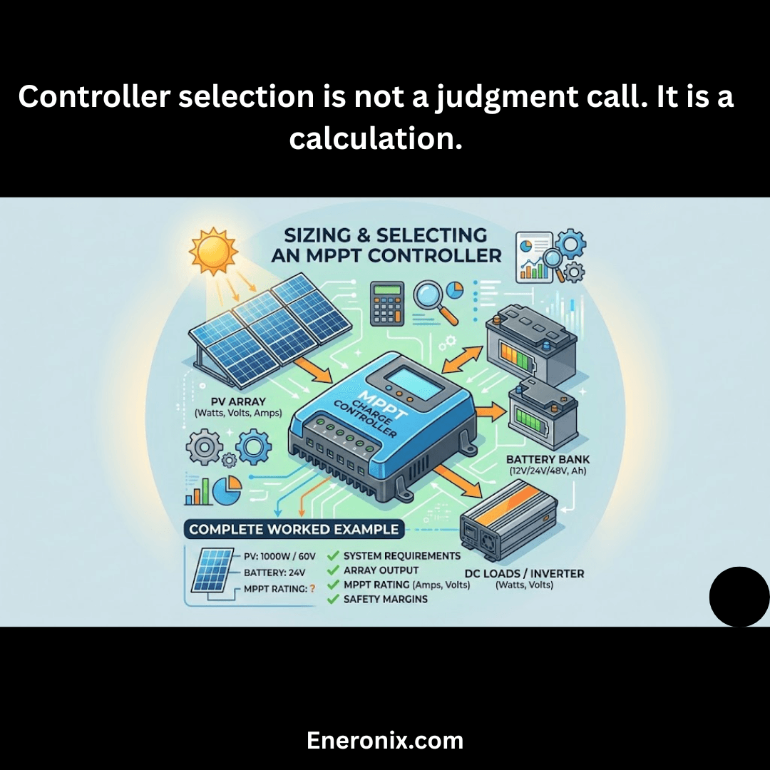
What the worked example demonstrates is that controller selection is not a judgment call. It is a calculation. The required output current is derived from the derated array output at the system voltage. The input voltage window compliance is derived from the string configuration and the site temperature envelope. The oversizing ratio is derived from the array STC rating and the controller’s rated output power. The thermal margin is derived from the installation environment and the controller’s published derating curve. Each of these produces a number, and each number either passes or fails against the controller’s published specification. There is no ambiguity in the result and no room for optimism in the inputs.
The six field failure modes documented in Section 9 share a common root cause: a step in this verification sequence was skipped. The output current was sized to STC rather than derated output. The cold Voc was not temperature-corrected. The product family was specified without verifying the model tier. Each omission is avoidable, and the framework in this post is the tool that avoids it.
In the next post in this series we move to inverter selection, applying the same constraint-based framework to the component that determines how the battery system’s stored energy reaches the loads.
For the array sizing, string configuration, and controller specification methodology this post builds on, refer to our engineering guides on how to size a solar array for an off-grid lithium battery system, series vs parallel vs series-parallel solar array wiring, and how MPPT charge controllers work and how to select the right one.

I am Engr. Ubokobong Ekpenyong, a solar specialist and lithium battery systems engineer with over five years of hands-on experience designing, assembling, and commissioning off-grid solar and energy storage systems. My work focuses on lithium battery pack architecture, BMS configuration, and system reliability in off-grid and high-demand environments.