How to Use This Checklist
Quick Reference:

10 sequential stages covering every phase from load audit to documentation handover

Each stage: pass criteria + verification method + reference post

Checklist must be completed IN SEQUENCE  no stage may be skipped

Measured values must be recorded in the field against each criterion

A stage cannot be signed off until ALL its pass criteria are met

Print this checklist. Carry it to site. Record values. Sign each stage.
Introduction
This checklist is the distillation of the entire cluster. Every pass criterion in it was derived from a calculation or verification step documented in one of the preceding eighteen posts. The cold Voc pass criterion in Stage 2 comes from the voltage calculation in the MPPT controller sizing guide. The fuse rating pass criterion in Stage 6 comes from the fusing rule in the DC cable sizing guide. The CVL/CCL/DCL pass criterion in Stage 4 comes from the BMS communication architecture in the battery bank sizing guide. The Off-Grid System Design Checklist does not replace those posts. It consolidates their verification steps into a single field document that can be completed without reference to any other source.
The ten mistakes documented in common off-grid system mistakes and how to avoid them are all prevented by this checklist. Every mistake maps to a specific stage and a specific pass criterion. A system that passes every criterion in this checklist will not produce any of those ten mistakes. The checklist is a field tool print it, carry it to site, and complete it with measured values recorded against each criterion before the project moves to the next stage.
Stage 1: Load Audit Checklist

The load audit establishes the daily energy demand figure that every downstream sizing calculation uses. No component can be correctly specified until this stage is complete and signed off. A load audit completed after the array and battery have been selected is not a load audit, it is a post-hoc justification of decisions already made.
| S/N | Criterion | Verification Method | P/F |
| 1.1 | All loads identified with measured running power (W), duty cycle (%), and daily usage hours | Clamp meter or plug-in power meter during normal operation — not at startup | |
| 1.2 | Motor loads separately identified: ACs, pumps, refrigerators, compressors | Visual inspection plus equipment specifications; confirm motor type for each | |
| 1.3 | Starting surge current estimated: 6x running for direct-on-line, 3x with soft starter | Calculate from measured running current or nameplate; document per load | |
| 1.4 | Phantom and standby loads identified with 24-hour daily energy contribution (Wh/day) | Clamp meter measurement at 22:00–02:00 with all deliberate loads off | |
| 1.5 | Peak simultaneous load calculated: sum of all loads that could plausibly run at once (W) | List all simultaneously active loads; sum running powers | |
| 1.6 | Worst-case surge demand: P_peak_running + (P_largest_motor x inrush_factor) | Calculate and document; this governs inverter surge specification | |
| 1.7 | Daily energy demand calculated: Σ(P_load x duty_cycle x daily_hours) for all loads including standby | Sum all contributions; units = Wh/day | |
| 1.8 | E_daily documented and agreed with client before any sizing proceeds | Written record with date and client acknowledgement |
Stage 1 Sign-off: E_daily = _________ Wh/day | Signed: _________________ | Date: _________
References: Load audit guide | Peak load vs average load | Phantom loads and standby power
Need a calculator to help you accurately calculate all this loads and data needed? We have a ton of high quality free calculators you can use here click here to access the tool.
Stage 2: Array Sizing Checklist

The array sizing stage confirms that the solar array produces sufficient derated daily harvest to meet the daily energy demand. Every calculation in this stage uses the E_daily figure signed off in Stage 1. A string configuration that passes all checks in this stage can be ordered and installed without revision.
| # | Criterion | Verification Method | P/F |
| 2.1 | Peak sun hours confirmed for location and worst-case season | PSH reference data; use rainy season figure not annual average | |
| 2.2 | Derating factor calculated: f_temp x f_soiling x f_mismatch x f_wiring | 0.89 x 0.95 x 0.98 x 0.98 = 0.813; apply site-specific adjustments | |
| 2.3 | Minimum array power: E_daily / (PSH x derating) | Calculate and document minimum array power required | |
| 2.4 | Panel count selected with 10-15% design margin above minimum array power | N_panels = (min array power x 1.10) / panel rated power; round up | |
| 2.5 | String configuration documented: N_series x N_parallel x panel power = total array power | Calculate and confirm total installed array power | |
| 2.6 | Cold Voc < 90% of MPPT controller max input voltage | Voc_cold = N_s x Voc_STC x (1 + coeff_Voc x (T_min – 25°C)) < 0.90 x V_ctrl_max | |
| 2.7 | Hot Vmp > MPPT controller minimum tracking voltage | Vmp_hot = N_s x Vmp_STC x (1 + coeff_Vmp x (T_cell_max – 25°C)) > V_ctrl_min | |
| 2.8 | Derated daily harvest ≥ E_daily: array power x derating x PSH ≥ E_daily | Calculated harvest must exceed Stage 1 daily demand figure | |
| 2.9 | Both Voc and Vmp checks PASS before MPPT controller is ordered | Criteria 2.6 and 2.7 must both show PASS before procurement proceeds |
Stage 2 Sign-off: Array: ___S x ___P x ___W | Cold Voc: ___V | Hot Vmp: ___V | Harvest: ___Wh/day | Signed: _________________ | Date: _________
References: Solar array sizing | Series vs parallel wiring
Stage 3: MPPT Controller Checklist
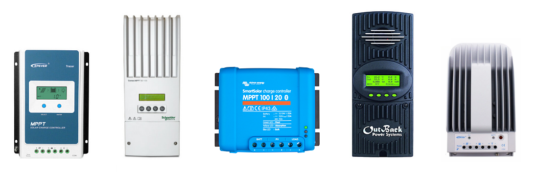
The MPPT controller stage confirms that the selected controller can accept the array’s output voltage under all temperature conditions, deliver the required charge current after thermal derating, and communicate with the Cerbo GX to enforce BMS charge limits. All checks must pass before the controller is ordered.
| # | Criterion | Verification Method | P/F |
| 3.1 | Cold Voc below 90% of controller maximum input voltage | From Stage 2.6: Voc_cold < 0.90 x V_controller_max | |
| 3.2 | Hot Vmp above controller minimum MPPT tracking voltage | From Stage 2.7: Vmp_hot > V_controller_min_tracking | |
| 3.3 | Combined array output current below controller derated output current | I_output = (P_array x derating) / V_battery < I_controller_derated | |
| 3.4 | Thermal derating applied at installation ambient temperature | I_derated = I_rated x (1 – 0.025 x (T_ambient – 45)) if T_ambient > 45°C | |
| 3.5 | Oversizing ratio within acceptable range | P_array / (I_controller x V_battery) ≤ 1.30; clipping check | |
| 3.6 | Controller firmware confirmed current before commissioning | Check Victron firmware release notes; update if required | |
| 3.7 | BMS protocol confirmed compatible with Cerbo GX supported battery list | Verify battery on Victron supported battery list before ordering | |
| 3.8 | Fallback charge profile: absorption voltage below BMS CVL | VictronConnect: absorption ≤ CVL – 0.4V; float below absorption | |
| 3.9 | VE.Can connection to Cerbo GX confirmed on device list | Cerbo GX device list shows controller with correct parameters | |
| 3.10 | No high voltage alarms after 30 minutes of operation | Monitor Cerbo GX alarm log after first activation |
Stage 3 Sign-off: Controller: _________ | Output current derated: ___A | Required: ___A | Signed: _________________ | Date: _________
Reference: MPPT controller sizing worked example
Stage 4: Battery Bank Checklist
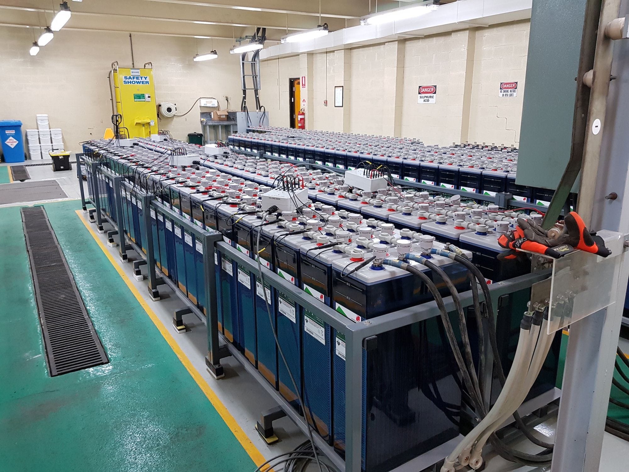
The battery bank stage confirms usable capacity, DoD, BMS communication, and installation temperature. Criterion 4.7 is the single most critical pass criterion in the entire checklist, no charge source may be activated until CVL, CCL, and DCL are confirmed on the Cerbo GX device list.
| # | Criterion | Verification Method | P/F |
| 4.1 | Nameplate x DoD ≥ E_daily x autonomy days | e.g. 14,200Wh x 0.90 ≥ 4,916Wh x 2 = 9,832Wh | |
| 4.2 | Daily DoD = E_daily / (nameplate x DoD_usable) < 80% | Calculate and document daily DoD | |
| 4.3 | Maximum four strings per BMS unit confirmed | N_units per BMS ≤ 4; additional BMS required if more than 4 units | |
| 4.4 | All BMS units connected via VE.Can-to-CAN adapters; one adapter per BMS | Physical inspection; all adapters on Cerbo GX VE.Can bus | |
| 4.5 | BMS firmware confirmed current before commissioning | Check manufacturer firmware release notes; update if required | |
| 4.6 | Pylontech BMS appears on Cerbo GX device list | Navigate to Cerbo GX device list before activating charge sources | |
| 4.7 ★ | CVL confirmed: 57.6V (16 x 3.60V/cell) — DO NOT ACTIVATE CHARGE SOURCES IF ABSENT | Cerbo GX device list shows CVL = 57.6V; if absent do not proceed | |
| 4.8 | CCL confirmed: N_units x 25A per unit | Cerbo GX device list shows correct CCL value for bank size | |
| 4.9 | DCL confirmed: N_units x 37A per unit | Cerbo GX device list shows correct DCL value for bank size | |
| 4.10 | Fallback charge profile programmed on all charge sources | Absorption ≤ CVL – 0.4V; charge current ≤ CCL on each source | |
| 4.11 | Battery enclosure ambient temperature below 37°C | Thermometer at enclosure height during dry season afternoon peak | |
| 4.12 | Individual 50A MIDI fuse per Pylontech US3000C unit at positive busbar | Visual inspection before energisation |
Stage 4 Sign-off: Bank: ___Wh | Daily DoD: ___% | CVL: ___V | CCL: ___A | DCL: ___A | Signed: _________________ | Date: _________
Reference: Battery bank sizing for off-grid systems
Stage 5: Inverter-Charger Checklist

The inverter-charger stage confirms continuous and surge capacity, DC voltage window, charge configuration, and AC output quality. The AC input current limit in criterion 5.6 must be verified against the actual generator that will be connected — a correctly sized inverter with an incorrectly set AC input current limit will overload the generator on the first automatic start.
| # | Criterion | Verification Method | P/F |
| 5.1 | Continuous rating > peak simultaneous load at 75% utilisation | P_peak < inverter_VA x 0.75; e.g. 1,950W < 3,000VA x 0.75 = 2,250VA | |
| 5.2 | Surge rating > peak simultaneous load + largest motor inrush | P_surge = P_peak + (P_motor x inrush); P_surge < inverter surge rating | |
| 5.3 | Soft starter on all motor loads above 1kW running power | Confirm soft starter on AC, pump, and any motor > 1kW | |
| 5.4 | LVC setting above BMS low voltage protection: LVC ≥ BMS LVP + 0.4V | e.g. LVC = 44.0V if BMS LVP = 43.6V; verify in VEConfigure | |
| 5.5 | HVC setting below BMS high voltage protection: HVC ≤ BMS HVP – 0.4V | e.g. HVC = 58.0V if BMS HVP = 58.4V; verify in VEConfigure | |
| 5.6 | AC input current limit calculated and set in VEConfigure | I_limit = (P_gen x 0.80 / V_AC) – I_AC_load; rounded down to integer | |
| 5.7 | Standby power acceptable: P_standby x 24h < 10% of E_daily | e.g. 15W x 24h = 360Wh < 491Wh (10% of 4,916Wh) | |
| 5.8 | Transfer time below 20ms for systems with computers or VFDs | Multiplus-II internal transfer switch: < 20ms by specification | |
| 5.9 | Waveform pure sine wave: THD < 3% | Multiplus-II specification; verify with power analyser if required | |
| 5.10 | CVL/CCL distributed to inverter via VE.Bus from Cerbo GX confirmed | Cerbo GX shows Multiplus-II receiving CVL and CCL from BMS | |
| 5.11 | AC output voltage: 230V ±2% at distribution board incomer | Calibrated AC voltmeter at distribution board terminals | |
| 5.12 | AC output frequency: 50Hz ±0.5Hz | Calibrated frequency meter at distribution board terminals |
Stage 5 Sign-off: Model: _________ | Peak: ___W | Surge demand: ___W | Surge rating: ___VA | AC input limit: ___A | Signed: _________________ | Date: _________
References: How to select off-grid inverter | Inverter sizing worked example
Stage 6: DC Wiring Checklist

The DC wiring stage confirms that every cable run satisfies both the thermal and voltage drop constraints simultaneously, every fuse is rated to protect the cable not the load, and the earth bonding has a single point at the inverter. Both constraints must pass for every run — a run that passes thermal but fails voltage drop is not a passing run.
| # | Criterion | Verification Method | P/F |
| 6.1 | Maximum circuit current identified for each run | From component specs: Isc for array, controller rated output, inverter I_DC | |
| 6.2 | Thermal derating: I_derated = I_rated x f_install x f_bundle x f_temp | Apply all three factors; derated value = thermal constraint minimum cross-section | |
| 6.3 | Voltage drop: A_min = (ρ x L x I) / V_drop_max | ρ = 0.0175 Ω·mm²/m; L = round-trip length; V_drop = 1% or 3% | |
| 6.4 | Cable cross-section = larger of thermal and voltage drop requirement | Both constraints must be satisfied; binding constraint governs | |
| 6.5 | Fuse rating: I_circuit_max < I_fuse ≤ I_cable_derated | Fuse protects cable not load; rating must not exceed cable derated current | |
| 6.6 | Fuse type: ANL above 80A, MIDI 30-80A, blade below 30A | Verify fuse holder interrupting capacity ≥ battery prospective short circuit current | |
| 6.7 | String fuses at combiner: 1.25 x Isc per string, individual per string | Individual string fuse per string; protects against reverse current |
Cable Run Summary:
| Run | Current | Cable | Thermal OK | VDrop OK | Fuse | Pass/Fail |
| String to combiner | ___A | ___mm² | ___A string | |||
| Combiner to MPPT | ___A | ___mm² | ___A MIDI | |||
| MPPT to battery | ___A | ___mm² | ___A ANL | |||
| Battery to inverter | ___A | ___mm² | ___A ANL | |||
| Battery to DC loads | ___A | ___mm² | ___A blade |
| # | Additional DC Wiring Criterion | Verification Method | P/F |
| 6.8 | Prospective short circuit current calculated: I_sc = V_battery / R_internal | Calculate and document; all hardware must be rated above this figure | |
| 6.9 | ANL fuse holders rated above prospective short circuit current | Verify fuse holder spec against I_sc; automotive blade holders not acceptable | |
| 6.10 | Busbars rated for full simultaneous circuit current | Busbar continuous rating > sum of simultaneously active circuit currents | |
| 6.11 | All terminal lugs hydraulic or ratchet crimped with matched dies | Visual inspection; no plier-crimped lugs on cables above 10mm² | |
| 6.12 | Single earth bond at inverter terminal only — no additional bonds | Visual inspection; no additional bonds at battery enclosure or MPPT | |
| 6.13 | DC negative to earth voltage < 50mV at energisation | Calibrated multimeter: DC negative busbar to earth bar | |
| 6.14 | Busbar bolt torque checked to manufacturer specification | Torque wrench; record torque value in commissioning documentation |
Stage 6 Sign-off: All five runs PASS both constraints | Earth bond verified | DC negative to earth: ___mV | Signed: _________________ | Date: _________
Reference: DC cable sizing for off-grid solar systems: the two-constraint framework
Stage 7: AC Distribution Checklist
The AC distribution stage confirms that every circuit has RCBO protection, the neutral-earth link switches correctly, the earth electrode is below 10 ohms, and the cable routing and identification standards are met. An AC board with MCBs instead of RCBOs on socket circuits or a permanent neutral-earth link is not a compliant installation.
| # | Criterion | Verification Method | P/F |
| 7.1 | Incomer cable sized for full inverter output current: thermal and VDrop constraints applied | I_incomer = inverter VA / 230V; apply two-constraint framework | |
| 7.2 | Incomer MCB: I_incomer < I_MCB ≤ I_cable_derated | Verify MCB rating satisfies both conditions | |
| 7.3 | RCBO specified for every outgoing circuit — no MCB-only circuits on socket/outdoor/bathroom/kitchen | Visual inspection of distribution board protection devices | |
| 7.4 | RCBO rating per circuit: I_circuit < I_RCBO ≤ I_cable_derated; 30mA trip threshold | Verify per circuit; confirm 30mA earth leakage trip threshold | |
| 7.5 | Cable sizing per circuit: thermal and VDrop constraints satisfied; 90°C insulation | Two-constraint framework applied to every AC circuit | |
| 7.6 | Neutral-earth link switches with AC source: active in inverter mode, open in passthrough | Multiplus-II internal relay: test by switching source and measuring N-E voltage | |
| 7.7 | Type 2 SPD at incomer: minimum 20kA impulse current per mode; backup MCB fitted | Physical inspection and SPD specification verification | |
| 7.8 | Earth electrode impedance < 10 ohms | Dedicated earth resistance tester; result recorded in commissioning docs | |
| 7.9 | Earth continuity verified: low-resistance ohmmeter at every connection | Check before energisation; record resistance at each point | |
| 7.10 | DC system bond: inverter earth terminal to distribution board earth bar | Single conductor from Multiplus-II earth lug to earth bar; visual check | |
| 7.11 | AC/DC cable segregation: 50mm minimum separation or physical barrier | Inspect cable routes; measure separation at closest point | |
| 7.12 | Cable identification: line brown, neutral blue, earth green-yellow throughout | Visual inspection; deviations sleeved at every termination | |
| 7.13 | Distribution board labelled: every circuit with load description and RCBO rating | Visual inspection of board labelling | |
| 7.14 | All RCBOs tested with test button before energising loads | Each RCBO trips on test button press and resets correctly |
Stage 7 Sign-off: Earth electrode: ___Ω | N-E link switching confirmed: YES/NO | All RCBOs tested: YES/NO | Signed: _________________ | Date: _________
Reference: AC wiring for off-grid solar systems: cable sizing, earthing, protection, and distribution
Stage 8: Generator Integration Checklist
The generator integration stage confirms sizing, power quality under combined load at the inverter input terminals, and auto-start configuration. A generator that has not been measured under combined load at the inverter input terminals has not been commissioned.
| # | Criterion | Verification Method | P/F |
| 8.1 | Generator sized: (P_AC_load + P_charge) / 0.80 ≤ generator rating | Calculate combined demand at configured AC input limit; verify ≤ 80% | |
| 8.2 | AC input current limit set in VEConfigure | I_limit = (P_gen x 0.80 / V_AC) – I_AC_load; rounded down | |
| 8.3 | Generator voltage at Multiplus-II input terminals under combined load: 210V to 250V | Calibrated AC voltmeter at inverter terminals — NOT generator output terminals | |
| 8.4 | Generator frequency under combined load: 49.5Hz to 50.5Hz | Frequency meter at inverter terminals under full combined load | |
| 8.5 | Generator accepted by Multiplus-II and passthrough confirmed | Cerbo GX shows AC input active and battery charging at configured limit | |
| 8.6 | Transfer time < 20ms: generator to inverter mode on generator stop | Power quality logger or stopwatch with AC indicator; measured value recorded | |
| 8.7 | Auto-start SoC trigger configured: < 30% for 5 continuous minutes | Cerbo GX generator start/stop settings; verify trigger value | |
| 8.8 | Stop condition configured: SoC > 80% AND minimum run time ≥ 30 minutes | Cerbo GX generator start/stop settings; verify both conditions | |
| 8.9 | Start failure alarm: VRM alert after 3 consecutive failed start attempts | VRM alert configuration; test by disabling generator and triggering start | |
| 8.10 | Run hour alert: VRM alert at 240 cumulative hours | VRM alert configuration; verify 240-hour threshold set | |
| 8.11 | Phase sequence verified for three-phase systems | Phase sequence indicator at inverter AC input terminals before first start |
Stage 8 Sign-off: Generator: ___kVA | AC input limit: ___A | Voltage under load: ___V | Frequency: ___Hz | Signed: _________________ | Date: _________
Reference: Generator integration, sizing, and hybrid operation for off-grid solar systems
Stage 9: System Commissioning Sequence Checklist
The commissioning sequence stage confirms that all seven commissioning stages have been completed in order with measured values recorded. No stage may be skipped or reordered. The values recorded here become the baseline for all future fault diagnosis.
| Stage | Description | Measured Values to Record | P/F |
| Stage 1 | Pre-energisation checks | Cable torque: confirmed / Earth continuity: ___Ω / All connectors seated: YES/NO | |
| Stage 2 | BMS communication verification | CVL: ___V / CCL: ___A / DCL: ___A / BMS on device list: YES/NO | |
| Stage 3 | MPPT controller activation | String voltage: ___V / Charge current: ___A / HV alarm after 30 min: YES/NO | |
| Stage 4 | Inverter activation | AC output voltage: ___V / Frequency: ___Hz / Waveform pure sine: YES/NO | |
| Stage 5 | AC load connection | All circuits connected: YES/NO / RCBO trips: YES/NO / Total load reading: ___W | |
| Stage 6 | Generator integration test | Transfer confirmed: YES/NO / Charge current: ___A / Transfer time: ___ms | |
| Stage 7 | VRM configuration | Portal registered: YES/NO / Alerts configured: YES/NO / Config exported: YES/NO |
| # | Additional Commissioning Criterion | Verification Method | P/F |
| 9.1 | Each stage completed before next stage activated — no stages skipped | Sequential completion confirmed; sign-off dates in correct order | |
| 9.2 | Stage 2 CVL/CCL/DCL confirmed before Stage 3 MPPT activation | Stage 2 sign-off date earlier than Stage 3 sign-off date | |
| 9.3 | MPPT active 30 minutes with no alarms before inverter activated | Monitor Cerbo GX alarm log; confirm no HV or communication alarms | |
| 9.4 | AC circuits connected individually with load reading verified per circuit | Cerbo GX load reading increases by expected amount per circuit added | |
| 9.5 | Transfer time below 20ms confirmed — measured value recorded, not assumed | Measured value in Stage 6 row of commissioning table above | |
| 9.6 | VRM portal shows live data from all three communication interfaces | MPPT, Multiplus-II, and BMS all visible in VRM portal simultaneously | |
| 9.7 | All commissioning alarm events reviewed and resolved | Cerbo GX alarm log reviewed; all alarms explained and cleared |
Stage 9 Sign-off: All 7 stages complete: YES/NO | CVL at commissioning: ___V | AC output: ___V | Transfer time: ___ms | Signed: _________________ | Date: _________
Reference: Off-grid solar system commissioning and troubleshooting: the complete field guide
Stage 10: Documentation Checklist
The documentation stage confirms that all five required commissioning documents have been produced, reflect the actual installed system, and are in the client’s possession before handover sign-off. Documentation produced after handover from memory is not commissioning documentation.
| # | Document | Content Requirement | In Client’s Possession | P/F |
| 10.1 | As-built wiring diagram | Actual cable cross-sections, fuse ratings, component model and serial numbers; reflects installed system not design intent | YES / NO | |
| 10.2 | Commissioning test results | Measured values and PASS/FAIL for all 7 stages; instrument used, time, technician name for each measurement | YES / NO | |
| 10.3 | Cerbo GX configuration export | All programmed parameters including charge profiles, alert thresholds, AC input limit, BMS communication config; exported to file | YES / NO | |
| 10.4 | VRM portal credentials | System ID, client account login, alert configuration confirmed; system ID NOT stored only on installer’s account | YES / NO | |
| 10.5 | Serial numbers and warranty registrations | Serial number of every major component; warranties registered in CLIENT’s name not installer’s name | YES / NO |
| # | Additional Documentation Criterion | Verification Method | P/F |
| 10.6 | As-built diagram reflects actual installation | Cross-check diagram cable sizes against physically installed cables at minimum 3 points | |
| 10.7 | Stage 2 CVL/CCL/DCL values present in commissioning test results | BMS communication confirmation is the single most important entry | |
| 10.8 | VRM portal accessible from client’s device before handover sign-off | Client logs in on their own device; confirms live data visible | |
| 10.9 | Component warranties registered in client’s name | Confirmation email or registration certificate produced at handover | |
| 10.10 | Copy of all documents retained by installer | Installer retains one copy; client has one copy; one copy on VRM |
Stage 10 Sign-off: All 5 documents produced: YES/NO | Client has VRM access from own device: YES/NO | Signed: _________________ | Date: _________
Reference: Off-grid solar system commissioning and troubleshooting: the complete field guide
Common Mistakes Cross-Reference
The ten common mistakes documented in common off-grid system mistakes and how to avoid them are each prevented by a specific criterion in this checklist:
| Mistake | Stage | Criterion | Prevention |
| Load audit using nameplate wattage | Stage 1 | 1.1 | Measured running power required, not nameplate |
| Phantom loads omitted | Stage 1 | 1.4 | Standby loads explicitly required with 24-hour energy contribution |
| Battery sized to nameplate without DoD | Stage 4 | 4.1 | Nameplate x DoD ≥ E_daily x autonomy days required |
| Inverter sized to average load | Stage 5 | 5.1, 5.2 | Peak simultaneous load and surge demand both required |
| DC cable thermally undersized | Stage 6 | 6.2, 6.4 | Thermal derating required; binding constraint determines specification |
| Fuse rated to load not cable | Stage 6 | 6.5 | Fuse rating must not exceed cable derated current |
| Multiple earth bond points | Stage 6 | 6.12, 6.13 | Single bond confirmed; DC negative to earth measured |
| BMS communication not verified | Stage 4, 9 | 4.7, 9.2 | CVL/CCL/DCL confirmed before charge sources activated |
| Commissioning documentation not produced | Stage 10 | 10.1–10.5 | All five documents required before handover sign-off |
| Expansion without constraint analysis | All stages | All | As-built documentation enables constraint analysis for future expansions |
Frequently Asked Questions

Can I use this checklist for a commercial system?
Yes. Every stage applies to commercial systems without modification. Commercial systems require additional criteria in Stage 1 for motor load surge analysis and standby load identification, and Stage 5 requires a three-phase inverter configuration check. Refer to how to size an off-grid solar system for commercial buildings for the commercial-specific additions to Stages 1 and 5.
At what stage should I order components?
Stage 2 must be complete before the MPPT controller and panels are ordered — the cold Voc and hot Vmp checks in criteria 2.6 and 2.7 may eliminate the initially selected controller. Stage 5 must be complete before the inverter is ordered — the surge check in criterion 5.2 may require a larger unit or a soft starter addition that changes the inverter specification.
What do I do if a stage fails?
Identify the specific criterion that failed, apply the corrective action from the referenced post, recalculate the affected parameter, and re-verify the criterion before signing off the stage. Do not proceed to the next stage until the failure is resolved. A stage signed off with a known failing criterion is not a signed-off stage it is an undocumented liability.
How long does the checklist take to complete?
Design stages 1 through 5 take approximately 3 to 4 hours at the design table before installation begins. Installation stages 6 and 7 add no time if measurements are taken as each cable run is completed. Commissioning stages 8, 9, and 10 take approximately 2 to 3 hours on site. Total: 6 to 8 hours per installation. The time required to diagnose and rectify one of the ten common mistakes after installation is 4 to 8 hours per callback visit, not including component replacement time or travel.
Conclusion
A checklist is only as useful as the discipline with which it is applied. A checklist completed after installation, from memory, to confirm what was already done rather than to verify what should be done, is an administrative exercise. This checklist is a design tool and a verification tool simultaneously, it prevents mistakes at the stage where they are cheapest to correct, which is always the stage before the next one.
The ten stages in this checklist correspond to the ten areas where the most consequential off-grid system errors are made. Every criterion in every stage was derived from a failure mode documented somewhere in this cluster, a real callback, a real warranty dispute, a real system performing below its specification because one calculation was skipped or one measurement was not taken.
Every post in this cluster is referenced at least once in this checklist. The methodology is complete. The verification framework is complete. The only remaining variable is whether the checklist is used.
For the underlying engineering methodology that each stage in this checklist is built on, refer to the complete cluster index at designing an off-grid power system using lithium batteries, which links to every post in this series.

I am Engr. Ubokobong Ekpenyong, a solar specialist and lithium battery systems engineer with over five years of hands-on experience designing, assembling, and commissioning off-grid solar and energy storage systems. My work focuses on lithium battery pack architecture, BMS configuration, and system reliability in off-grid and high-demand environments.