Temperature creates invisible conflicts between BMS protection and inverter control. Batteries in garages show 12-18% capacity fade versus 2% for climate-controlled installations. Here’s why temperature is your silent enemy.
The Silent Degradation Pattern
Monitoring data from 150 residential solar installations over 18 months reveals a pattern most installers miss. Batteries in climate-controlled spaces show 2% capacity fade after one year, matching normal LFP aging expectations. Batteries in non-climate-controlled garages and sheds show 12-18% capacity fade in the same timeframe, six to nine times faster degradation.
Same battery models, same inverters, same installation quality. The only variable: temperature exposure. Garage installations experience -5°C winter mornings and 45°C summer afternoons. Climate-controlled installations stay between 15-25°C year-round. The 30-50°C temperature swing doesn’t just reduce immediate performance. It accelerates aging through multiple mechanisms that compound over time.
Temperature affects current sensor accuracy, introducing ±2A offset errors that accumulate into 15% SOC drift over weeks. Cold weather triggers lithium plating during charging below 0°C, causing irreversible 1-2% capacity loss per incident. Hot weather accelerates calendar aging, doubling degradation rate above 40°C. Each temperature extreme creates stress, and most systems experience both extremes seasonally.
The communication challenge emerges from conflicting temperature data. BMS measures cell surface temperature at 42°C and reduces CCL to 60A for thermal protection. Inverter measures ambient temperature at 28°C in its air-conditioned location and applies its own compensation, increasing the received 60A limit back to 85A. The inverter charges at 85A while the BMS expected 60A maximum. Cell temperature climbs to 47°C, approaching the 50°C emergency disconnect threshold.
Cost of temperature mismanagement appears gradually. Battery replacement at year 6 instead of year 12 costs $8,000-$15,000. Reduced usable capacity from imbalance and degradation frustrates customers who expected full performance. Service calls for ‘battery not charging’ during cold mornings cost $300-$500 per diagnostic visit. The expensive part is not the immediate failure but the accumulated damage over months that appears as premature aging rather than configuration error.
The Dual Compensation Conflict
BMS measures cell temperature at 38°C and reduces CCL from 100A to 80A for thermal protection. BMS transmits CCL = 80A. Inverter measures ambient temperature at 28°C in climate-controlled equipment room. Inverter firmware applies compensation assuming cooler conditions and increases received 80A to 95A. Inverter charges at 95A while BMS expected 80A maximum. Cell temperature climbs toward danger threshold.
This conflict appears in 30% of installations. Problem intensifies when batteries occupy unconditioned spaces while inverters stay indoors. Temperature delta reaches 20-30°C during extremes.
Why This Happens
BMS temperature compensation is built into transmitted limits. BMS measured 38°C, calculated 80A safe maximum, sent that value. Inverter receives 80A without knowing it’s already compensated. Inverter applies second compensation layer assuming it received raw base limit. Corrections work against each other.
Real field example shows consequences. Hot summer day, battery compartment 45°C. BMS correctly limits CCL to 40A. Inverter in air-conditioned space measures 22°C ambient. Inverter logic: 22°C is cold, battery can handle more. Inverter multiplies 40A by 1.5× boost factor. Charges at 60A. Battery reaches 48°C. BMS emergency disconnect at 50°C.
BMS is authoritative: measures actual cell temperature, correctly calculates safe limits. Inverter measures irrelevant ambient temperature. But inverter firmware cannot distinguish compensated from uncompensated limits. For detailed explanation of how CVL, CCL, and DCL limits work and update in real-time, see the comprehensive guide on dynamic battery limits.
Understanding CCL and DCL Temperature Curves
Charge current limits reduce with temperature following specific curves. At 25°C optimal temperature, LFP accepts 100% rated current (200A for 200Ah battery). At 15°C: 80% or 160A. At 5°C: 50% or 100A. At 0°C: 10% or 20A in plating danger zone. Below 0°C: 0A mandatory to prevent plating.
Why these values: above 15°C shows minimal plating risk allowing full performance. Between 5-15°C, plating probability increases requiring safety margin. Between 0-5°C, significant plating risk permits minimal charging. Below 0°C, plating occurs at any current making charging forbidden.
Discharge permits higher current than charge. At 25°C: 100% or 200A. At 5°C: 85% or 170A. At -10°C: 60% or 120A. At -20°C: 30% or 60A. Discharge allows more because no plating risk exists. Only limitation is voltage drop from resistance. Cold discharge causes no permanent damage, just reduced capacity.
Hot weather charge derating protects differently. At 35°C: 80% or 160A. At 40°C: 60% or 120A. At 45°C: 40% or 80A. At 50°C: 10% or 20A or 0A. Above 50°C: all charging stops. High temperature charging generates heat from losses and accelerates calendar aging. SEI growth accelerates above 40°C. Thermal runaway risk increases above 50°C.
Temperature hysteresis prevents oscillation. Simple threshold problem: CCL drops from 100A to 40A at 45°C. Temperature oscillates 44.8-45.2°C. CCL oscillates causing inverter instability. Solution: reduce CCL at 45°C but restore only when temperature drops to 42°C. The 3°C hysteresis prevents rapid changes ensuring smooth operation.
The Solution: Disable Inverter Compensation
Inverter-side compensation should never increase limits above received BMS values, only decrease. This reinforces BMS authority for protection decisions.
Configuration solutions require disabling inverter thermal compensation entirely. Trust BMS sensing at cells. Configure inverter to use received limits without modification. Requires finding hidden menu settings often undocumented. Not all inverters allow disabling. Alternative: move inverter temperature sensor to battery compartment or wire external sensor to BMS temperature output. Makes both see identical temperature, reduces conflict.
Cold Weather: The Lithium Plating Catastrophe
Lithium plating occurs when lithium ions moving from cathode to anode during charge cannot intercalate into graphite anode structure fast enough. Below 0°C, intercalation kinetics slow dramatically. Ions arrive faster than they can insert into the graphite lattice. Metallic lithium deposits on anode surface instead, a process called plating.
Plating causes permanent damage. Plated lithium does not participate in future charge-discharge cycles, representing irreversible capacity loss. Plated lithium forms dendrites that grow toward the cathode, potentially piercing the separator and causing internal short circuits. Even without shorts, plated lithium consumes electrolyte through side reactions. Each cold charge cycle causes 1-3% irreversible capacity fade that accumulates over time.
Critical Temperature Thresholds for Charging
Above 5°C: Minimal plating risk at reasonable charge rates below 0.5C. Full CCL permitted.
0-5°C: Significant plating risk appears above 0.1C (20A for 200Ah cells). Reduce CCL to 50% maximum.
Below 0°C: High plating risk exists at ANY charge current including trickle charging. CCL must equal 0A.
Below -10°C: Plating occurs even at 5A. Mandatory charging block.
When Protection Fails
Winter scenario: morning temperature -3°C, BMS sets CCL = 0A, solar production starts, inverter has 5A minimum charge current floor, inverter charges at 5A despite CCL = 0A. Lithium plating occurs for 2-3 hours until ambient temperature rises.
After one winter with 30 cold mornings: cumulative damage reaches 1.5% per cycle × 30 cycles = 45% total capacity loss. Battery appears to have failed prematurely when actually damaged from repeated cold charging that proper CCL enforcement would have prevented.
Proper BMS protection measures cell temperature, not ambient. If temperature reads below 0°C, BMS sets CCL = 0A and transmits this to the inverter. If inverter ignores the limit, BMS opens charge path through contactor control. Advanced systems use pre-heating strategies, applying discharge current to self-heat the pack or activating resistive heating elements. Typical heating time runs 15-30 minutes to raise cells from -5°C to above 5°C before allowing charge.
Communication of Blocked State
CCL = 0A could mean temperature protection, battery full, or fault condition. Better protocol implementations include temperature value plus explicit ‘charge blocked – too cold’ status flag allowing inverter to display appropriate user message instead of generic ‘battery communication error’ that sends installers checking cables for hours.
The communication ambiguity creates service call nightmares. Customer calls: ‘Battery won’t charge.’ Installer arrives, checks CAN termination (60Ω, correct), checks cable continuity (good), checks DIP switches (correct), checks firmware versions (compatible), spends 2 hours troubleshooting. Finally checks battery temperature display: -3°C. CCL = 0A is protection, not fault. Bill customer $300-$500 for diagnostic time that temperature check would have caught in 30 seconds.
Hot Weather: Thermal Runaway Protection
Thermal runaway progresses through distinct stages requiring different communication-based protections at each level. Understanding these stages prevents catastrophic failure.
Temperature Protection Stages
Stage 1 (40-45°C): Accelerated Aging
Normal elevated temperature where accelerated calendar aging occurs without immediate danger. BMS should reduce CCL to slow internal heat generation and monitor temperature rate of rise. At 40°C: reduce CCL to 60%. At 45°C: reduce CCL to 40%.
Stage 2 (45-50°C): Critical Temperature
SEI layer decomposition begins and exothermic reactions start becoming self-sustaining. BMS should set CCL = 0A, reduce DCL significantly, and prepare to disconnect if temperature continues rising. At 48°C: block all charging. At 50°C: prepare emergency disconnect.
Stage 3 (50-60°C): Thermal Runaway Initiation
Internal exothermic reactions dominate. Temperature rises even with zero external current as chemical decomposition becomes self-heating. Cell venting begins with pressure relief valves activating. BMS must open contactors immediately and notify user or fire suppression system.
Stage 4 (Above 60°C): Full Thermal Runaway
Uncontrollable temperature rise to 200°C or higher. Smoke, flames, and toxic gas release occur. Cascade to adjacent cells happens without isolation. BMS can only disconnect and alert, cannot stop progression at this point.
Communication Failures During Thermal Events
When inverter ignores temperature alarms, dangerous scenarios develop. Battery temperature 47°C and climbing, BMS transmits CCL = 0A and critical temperature alarm, inverter receives message but firmware does not parse alarm flags. Inverter sees CCL = 0A and interprets as full battery. Solar production continues, inverter attempts charging. BMS contactors open for protection. Inverter sees disconnect as fault and retries connection.
Better inverter implementation parses alarm flags, distinguishes CCL = 0 due to temperature from CCL = 0 due to full charge, stops all attempts during critical alarms. For detailed analysis of how communication loss triggers different BMS response modes, see Communication Loss Modes: How Your Battery Degrades When Communication Fails.
Temperature Impact on Current Sensors and SOC Drift

Hall effect sensors measure current in 80% of battery systems through non-contact magnetic field detection. Specification shows ±1% accuracy at 25°C calibration temperature. Temperature effects degrade this dramatically outside calibration range.
Offset Drift: The Silent SOC Killer
Hall sensors drift ±50-200 microvolts per degree Celsius. At -10°C, the 35°C delta from calibration creates 1.75-7mV offset error, translating to ±0.5A to ±2A constant error. The sensor reads 1.5A when actual current is zero.
Why offset error destroys SOC accuracy: it shows current flowing when none exists. A 1.5A offset over 24 hours accumulates 36Ah false measurement. For a 200Ah battery, that’s 18% SOC error in one day from temperature alone. Error accumulates continuously because offset is directional bias, not random noise.
Field example shows compound effects. Winter morning at 5°C with sensor offset +2A and gain -2%. Actual current 0A but sensor reads +2A continuously. Over 10 hours: 20Ah error. Then 50A charging begins, sensor reads 49A from gain error. Over 3 hours: additional 3Ah error. Total 23Ah error equals 11.5% SOC drift, all from temperature effects on current measurement.
Gain Drift Compounds the Problem
Sensitivity changes ±0.1% to ±0.3% per degree Celsius. At 50A and -10°C, sensor reads 48.5A, a 3% error. At 45°C, same 50A reads as 51.5A. Combined with offset, total error reaches ±5% at temperature extremes.
Shunt resistors offer better base accuracy at ±0.2% to ±0.5% but face different issues. Resistance changes 20-50 ppm per degree Celsius. At 40°C delta, resistance shifts 0.08% to 0.2%. Self-heating at high current raises shunt temperature 5-10°C above ambient, creating variable error that’s difficult to compensate.
Good BMS firmware measures sensor temperature separately, applies offset correction, applies gain correction, and recalibrates zero when current actually zero. Cheap firmware uses factory 25°C calibration only with no compensation. The difference shows up as mysterious SOC drift that installers blame on communication failures when it’s actually uncompensated sensor temperature error.
For complete context on SOC drift mechanisms and coulomb counting errors, see SOC Drift in Lithium Battery Systems: Why Your BMS and Inverter Disagree.
Temperature-Compensated SOC: What Users Actually See
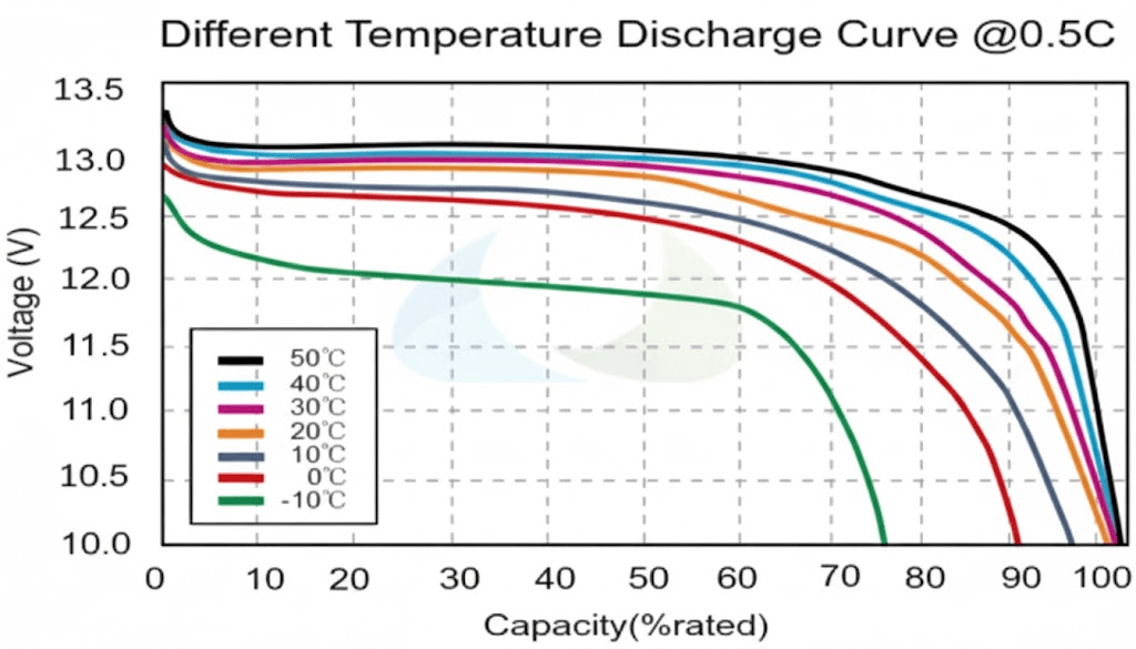
LFP capacity reduces significantly in cold weather. At 25°C, 200Ah battery delivers full 200Ah capacity. At 0°C: 85% or 170Ah. At -10°C: 70% or 140Ah. At -20°C: 50% or 100Ah. Internal resistance increases with cold, causing voltage drop at given current to increase. System hits low-voltage cutoff earlier.
The SOC calculation problem emerges from using fixed capacity values. User discharges 100Ah at -10°C. BMS shows 50% SOC remaining using 100Ah ÷ 200Ah. Reality: 71% of available capacity used because only 140Ah is accessible at -10°C. Only 40Ah remains accessible, not the 100Ah that SOC display implies.
Three Methods for Temperature-Compensated SOC
Method 1: Adjust Displayed SOC
Keep internal calculation using 200Ah base but adjust display based on temperature. At -10°C with 100Ah remaining, display 20% SOC showing realistic runtime expectation. User sees conservative estimate preventing unexpected shutdowns.
Method 2: Adjust Capacity Value
Recalculate total capacity based on temperature. At -10°C use 140Ah total instead of 200Ah. Then 100Ah remaining ÷ 140Ah total = 71% SOC. More accurate but confusing as capacity changes with temperature. User sees battery shrink and grow with weather.
Method 3: Hybrid Approach (Best)
Track both chemical SOC independent of temperature and available SOC temperature-compensated. Transmit both values if protocol supports. Inverter displays available SOC to user. BMS uses chemical SOC for internal decisions. This provides accurate user expectation while maintaining proper BMS control.
Real-World Impact of Wrong SOC
Current reality: most BMS transmit raw SOC without temperature compensation. Inverter receives optimistic value in cold weather. User thinks 50% battery exists but actually has 20% available. System shuts down unexpectedly because displayed SOC was wrong.
Winter morning scenario at -5°C shows 80% SOC representing 160Ah of 200Ah. Temperature-adjusted reality: 47% available as 160Ah ÷ 170Ah accessible at -5°C (LFP loses 15% capacity at -5°C). User draws 50Ah for heating. BMS shows 55% SOC but voltage drops rapidly from cold resistance. System hits cutoff at apparent 55% SOC. User confused, suspects defect when cold weather reduced capacity.
Sensor Placement: Surface vs Core Temperature
Where you measure temperature determines what you protect. BMS implementations use surface-mounted sensors, core-embedded sensors, or both depending on cost constraints and application requirements.
Surface Temperature Sensing
Surface temperature sensing dominates residential battery systems. NTC thermistor attaches to cell can exterior with adhesive or thermal paste, reading surface temperature directly. Response time runs 10-30 seconds for detecting temperature changes. Typical implementation uses one sensor per 4-8 cells distributed throughout the pack at $5-$15 per sensor.
Surface sensors excel at detecting external heating. Inverter waste heat radiating onto battery enclosure appears immediately. Direct sunlight through windows raises surface temperature before affecting core. Thermal runaway early warning comes from detecting hot spots where one cell surface diverges 5°C above neighbors.
What surface temperature misses: internal state during high current operation. Core temperature runs 5-15°C hotter than surface during sustained high-rate charge or discharge. A cell showing 35°C surface might have 45°C core approaching danger thresholds. Cold weather creates opposite error where surface reads -5°C but core remains at +2°C from thermal mass, causing over-conservative protection.
Dual Sensing Strategy for Commercial Systems
Commercial systems above 20 kWh increasingly use dual sensing. Surface sensors provide fast response and multiple measurement points for $40-$120 total. One or two core sensors add absolute accuracy for $100-$400. Use surface sensors for rate-of-change detection and hot-spot identification. Use core sensors for absolute limit enforcement and true thermal state.
If surface-core temperature delta exceeds 10°C during operation, reduce current immediately regardless of absolute temperature values. The temperature gradient itself indicates thermal stress requiring protective action.
Configuration Best Practices
BMS Configuration
- Minimum 4 sensors for packs above 10 kWh, distributed one per 4-8 cells
- Surface mount with thermal paste, not air gap
- Enable aggressive cold protection: 0A charging below 2°C instead of 0°C
- Enable hot protection: 0A charging above 48°C instead of 55°C
- Use smooth derating curves, not step functions
- Enable 3-5°C hysteresis preventing threshold oscillation
- Enable SOC temperature compensation if supported
Inverter Configuration
- Disable inverter temperature compensation entirely – trust BMS limits already adjusted
- Configure inverter to enforce received limits without modification
- Find battery temperature compensation setting, disable or set to BMS-controlled
- Configure inverter to recognize temperature alarm flags
- Display specific temperature fault messages, not generic communication errors
- Set inverter minimum charge current to 0A if possible
Physical Installation
- LFP generates 2-5W per kWh during operation – requires proper ventilation
- 10 kWh battery produces 20-50W heat requiring 50-100 CFM airflow
- Hot climates need active fans
- Cold climates need insulated enclosures and heating blankets (50-200W, 5°C setpoint)
- Install inverter remote sensor in battery compartment if available
- Avoid non-climate-controlled spaces in extreme climates
- Do not mount against sun-exposed walls
Diagnostic Approach: Temperature vs Communication
System offline with communication error? Check BMS temperature first. If below 0°C or above 50°C, likely protection not failure. Verify CCL and DCL values. CCL = 0A suggests temperature protection. True communication failure shows no data or stale timestamps.
Systematic Diagnosis Steps
1. Verify temperature readings from BMS display, inverter display, and infrared thermometer on actual cells. Compare for consistency. A 5°C difference indicates sensor problem.
2. Check temperature-based limits against expected curves. At 40°C expect CCL at 60-70% maximum. At 5°C expect 40-60%. Inconsistency indicates configuration error.
3. Review historical logs showing 30 days temperature data. Identify minimums and maximums reached. Check for charging during extremes. Cold charging = plating. Hot charging = accelerated aging.
Common Misdiagnoses
‘Battery won’t charge’ = Cold protection at -2°C. Installer checks termination, connections, firmware for 2 hours. Finally checks temperature showing CCL = 0A is protection not fault. Solution: wait for warmup or add heating.
‘Reduced capacity’ = Physics at -8°C (140Ah is normal 70% reduction from 200Ah rated), not degradation. Check if capacity returns when temperature normalizes.
‘Random shutdowns’ = Thermal protection cycling at 47-52°C, not communication errors. Add ventilation or cooling.
For systematic communication troubleshooting when temperature ruled out, see BMS-Inverter Communication Troubleshooting: Proven Solutions to Fix Connection Failures.
Conclusion
Temperature affects every aspect of battery communication and control: sensor accuracy degrades outside 15-30°C causing SOC drift, available capacity drops 30% at -10°C making displays optimistic, cold charging below 0°C causes permanent plating damage, and hot operation above 45°C accelerates aging. BMS and inverter measure different temperatures at different locations creating dual compensation conflicts where protection gets undone.
Most temperature problems get misdiagnosed as communication failures. CCL = 0A from cold protection appears as battery fault. Thermal cycling looks like random disconnects. Capacity reduction from cold weather appears as premature degradation. Diagnosis requires checking temperature first before investigating cables, termination, or firmware.
Configuration prevents damage: disable inverter temperature compensation trusting BMS limits, enable SOC temperature adjustment showing available capacity, add heating for climates below 0°C regularly, add cooling for climates above 40°C regularly, and monitor temperature alongside communication status.
Cost comparison: $2,000-$15,000 in battery replacement from plating or thermal damage versus $500-$2,000 for proper thermal management equipment.
For complete context on communication mechanisms, physical layer troubleshooting, and protocol implementation underlying temperature control, see Understanding Inverter Battery Communication Protocols in Modern Solar Systems.

Hi, i am Engr. Ubokobong a solar specialist and lithium battery systems engineer, with over five years of practical experience designing, assembling, and analyzing lithium battery packs for solar and energy storage applications, and installation. His interests center on cell architecture, BMS behavior, system reliability, of lithium batteries in off-grid and high-demand environments.