Introduction
Ever had an 8 PM site call. Battery system dead. The inverter reports a communication error. The customer is frustrated because it worked yesterday on the bench with a one meter cable.
Today’s installation uses a four meter run. Communication fails. You spend 90 minutes checking firmware versions, scrolling menus, reading DIP switch tables, and power cycling both devices.
Then you measure termination resistance. One hundred and twenty ohms. It should be sixty. One resistor is missing.
You bridge the jumper. Measure again. 60 ohms. Power up. Communication establishes instantly.
The fix took sixty seconds once you checked the physical layer.
This is the pattern. Roughly ninety percent of communication failures are not protocol issues. They are physical layer faults. Incorrect termination. Poor cable selection. Loose connectors. EMI pickup. These present as mysterious protocol errors.
The remaining cases are genuine incompatibilities or firmware defects. But you cannot diagnose those until the physical layer is verified.
This post outlines a systematic troubleshooting approach that resolves communication failures in minutes, not hours.
What This Post Covers
By failure frequency:
- Termination problems (40% of all failures)
- Cable quality and routing (15% of failures)
- Connection integrity, loose terminals, bad crimps (25% of failures)
- EMI and ground loops (10% of failures)
- Systematic 20-minute diagnostic procedure
Time investment: 20 minutes of physical checks solves 90% of problems. Compare that to 3+ hours debugging protocols when the issue is a missing termination resistor.
Also Read: SOC Drift in Lithium Battery Systems: Why Your BMS and Inverter Disagree
CAN bus termination troubleshooting
CAN (Controller Area Network) uses differential signaling on twisted pair wires: CAN-H and CAN-L. The signal is the voltage difference between them, not the absolute voltage.
Why differential matters: Electrical noise from inverter switching affects both wires equally. If noise adds +0.5V to CAN-H, it adds +0.5V to CAN-L simultaneously. The receiver subtracts one from the other, noise cancels out. This is why CAN works in electrically hostile environments.
Key specifications:
- Baud rate: 500 kbps (500,000 bits/second) standard for battery systems
- Max cable length: 100 meters (spec), 5-10 meters (reliable in real solar installations)
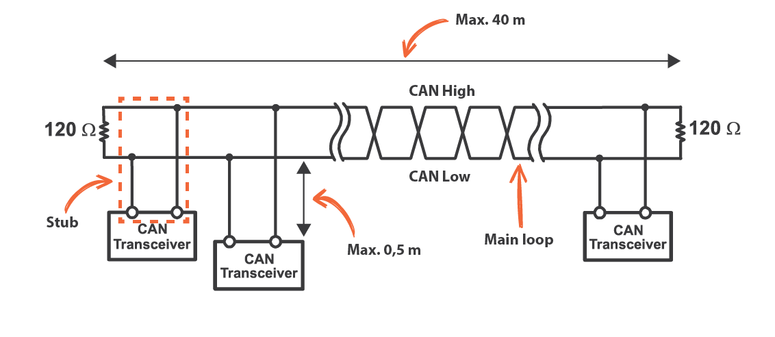
- Topology: Multi-drop bus, battery, inverter, monitoring system all share the same two-wire bus
- Termination: 120Ω resistor at each physical end (60Ω measured between CAN-H and CAN-L)
Understanding differential signaling explains why specific problems cause specific symptoms. Missing termination creates reflections. Ground loops inject common-mode noise. Poor cables can’t reject EMI. These aren’t random, they’re predictable physics.
Diagnostic Roadmap
Physical layer checks follow a hierarchy. Work from most common to least common:

Communication fails at commissioning:
- Verify protocol settings match exactly
- Measure termination (60Ω between CAN-H and CAN-L)
- Check cable length and quality
Communication fails intermittently:
- Test for EMI correlation (does it fail at high power?)
- Check for ground loops
- Verify cable routing away from DC bus
Communication worked for months, now fails:
- Re-torque screw terminals (thermal cycling loosens them)
- Inspect for corrosion at connections
- Check for physical cable damage
Termination: The 60-Ohm Rule
At 500 kbps, CAN bus is a transmission line. Signal wavelengths are tens of meters, comparable to cable lengths. Without proper termination, signals reflect from cable ends like sound echoing in a room. Reflections corrupt data.
Read: Inverter Battery Communication Protocols in Modern Solar Systems
Correct termination: 120Ω resistor at each physical end of the bus. Two resistors total.
How to measure: Power off both devices. Disconnect CAN cable from one end. Set multimeter to resistance mode. Measure between CAN-H and CAN-L. Should read 60Ω ±5Ω.
Why 60Ω? Two 120Ω resistors in parallel = 60Ω.
This single measurement identifies the four most common termination mistakes:
| Measurement | Problem | Failure Rate |
| Open circuit | No termination at all | >1m fails completely |
| 120Ω | Single termination (one end only) | <2m works, >3m fails |
| 40Ω | Triple termination (3+ resistors) | Works but marginal |
| 100Ω | Wrong value (Ethernet parts) | Impedance mismatch |
| 60Ω | Correct (two 120Ω resistors) | Reliable |
Where resistors hide: Inside RJ45 connectors, on BMS PCBs controlled by jumpers or DIP switches, on inverter boards, or inline on pre-made cables. You must locate them to verify proper termination.
Cable Quality: Not All Wire Is CAN Bus Cable
Proper CAN cable requires:

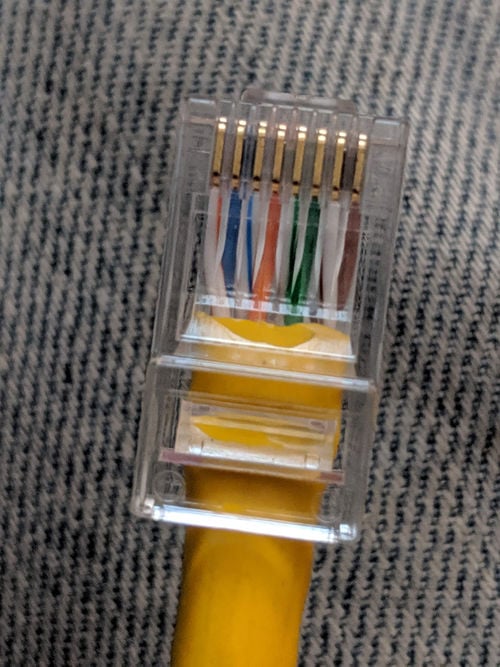
- Twisted pair construction (CAN-H and CAN-L twisted together, not parallel)
- 120Ω characteristic impedance (matched to termination resistors)
- 18-24 AWG wire gauge (adequate conductivity and strength)
- Shielding (recommended inside inverter enclosures)
What installers actually use:
| Cable Type | Why It Fails | Max Reliable Length |
| Speaker wire | Parallel conductors, no twisting | ~1 meter |
| Cat5/6 Ethernet | 100Ω impedance (not 120Ω) | 2-3 meters |
| Alarm cable | Minimal twist, no shielding | 1-2 meters |
| Belden 3105A | Proper 120Ω twisted pair, shielded | 5-10 meters |
Practical guideline: Keep cables under 3 meters. Use proper twisted pair (Belden 3105A, Alpha Wire 6712, or equivalent). Inside inverter enclosures, use shielded cable and keep runs under 2 meters.
Cable Routing: Minimize EMI Coupling
Wrong: CAN cable runs parallel to DC bus for 50cm or more
Right: Perpendicular crossings only. If cables must be near each other, separate by 10cm minimum
Avoid tight bends. Maintain minimum bend radius of 10× cable diameter. Sharp 90° bends damage conductors and create impedance discontinuities.
Connection Integrity: The Hidden Failure Mode
Connections that worked at installation fail after 6 months. Not dramatic failures, just gradual degradation from thermal cycling and corrosion.
Screw Terminals Loosen Over Time
Batteries heat up 10-15°C during charge/discharge, cool back down at rest. This expansion and contraction works screw terminals loose over months. Communication that was perfect at commissioning becomes intermittent.
Fix: Power off system. Remove CAN cables. Re-torque screws to spec (or finger-tight plus ¼ turn with screwdriver). Reconnect. Test.
Prevention: Include terminal re-torquing in 6-12 month maintenance schedule. Use spring-loaded terminals where possible.
Crimp Quality
Good crimp: Terminal barrel uniformly compressed around wire, no visible gaps, withstands 10-20 lbs pull force
Bad crimp: Visible gaps, terminal rotates or pulls off with moderate force, cracks in barrel from over-crimping
Test: Pull firmly on wire. Terminal should not move. If it does, re-terminate with proper ratcheting crimp tool.
Corrosion
Copper exposed to moisture forms green verdigris. Contact resistance increases from <5mΩ fresh to 50-500mΩ corroded. Develops over months in humid or coastal environments.
Fix: Clean with wire brush and contact cleaner. Seal with heat shrink or liquid electrical tape to prevent recurrence.
EMI and Ground Loops
When Problems Correlate with Power Level
Solar inverters generate severe EMI. MOSFETs switching at 20-100 kHz with hundreds of amps create broadband noise. This couples into nearby cables.
Diagnostic test: Does communication fail during high-power operation? If system works fine at 10A but fails at 100A, EMI is the problem. If errors are random regardless of power level, look elsewhere.
Solutions:
- Use shielded cable inside inverter enclosures
- Route CAN cable perpendicular to DC bus and AC output
- Keep cable runs as short as possible
Ground Loops
CAN bus has three conductors: CAN-H, CAN-L, and CAN-GND (reference ground). If CAN-GND connects at both battery and inverter ends, you create a ground loop.
During high current operation, battery ground and inverter ground can differ by several hundred millivolts. If CAN-GND connects both points, this voltage drives current through the CAN-GND conductor. That current creates magnetic field coupling that corrupts the differential signal.
Diagnostic: Measure voltage between battery ground and inverter ground during operation. >0.2V suggests ground loop contribution.
Fix: Connect CAN-GND at one point only (typically at inverter). Disconnect at battery end.
20-Minute Systematic Diagnostic Procedure
Work through this procedure in order. Each step takes minutes and solves specific failure modes.
Step 1: Configuration Checks (5 minutes)
- Inverter protocol setting matches BMS exactly (“Pylontech” ≠ “CAN Protocol”)
- Baud rate = 500 kbps on both devices
- DIP switch positions match manual (photograph current positions)
Step 2: Termination Check (2 minutes)
- Power off both devices completely
- Disconnect CAN cable from one device
- Multimeter to resistance mode
- Measure between CAN-H and CAN-L at disconnected cable end
- Should read 60Ω ±5Ω
If wrong, locate termination resistors and fix (add missing, remove extras).
Step 3: Cable Inspection (5 minutes)
- Verify cable is twisted pair (cut end if necessary to inspect)
- Check for physical damage (cuts, abrasion, sharp bends)
- Measure actual cable length including routing
- Verify routing: perpendicular crossings with DC bus only
Step 4: Connection Integrity (8 minutes)
- Re-torque all screw terminals (even if they look tight)
- Pull test all crimped connections
- Inspect for green or white corrosion deposits
Total time: 20 minutes. Success rate: 90% of communication problems solved.
Required Tools: Three-Tier Approach
Tier 1: Essential Tools ($50-150)
Every installer needs:
- Klein MM600 multimeter ($60) – Adequate accuracy for termination checks
- Ratcheting crimp tool ($80) – Ensures consistent crimps, won’t release until compression is complete
- Basic screwdriver set ($20) – For terminal access
Tier 2: Professional Tools ($200-500)
- CANable USB adapter ($60) – For message capture and protocol debugging
- Fluke 87V multimeter ($400) – Better accuracy and reliability than entry-level meters
Tier 3: When Clients Pay ($500+)
- PCAN-USB analyzer ($500) – Professional-grade protocol analysis with advanced triggering
Reality check: 90% of problems are solved with Tier 1 tools and 20 minutes. Only the remaining 10% need protocol analyzers, and those usually indicate incompatible devices, not fixable physical issues.
Installing It Right the First Time
Prevention is cheaper than troubleshooting. Follow these practices at installation to eliminate 90% of future problems:
Cable Selection
- Use proper 120Ω twisted pair CAN cable (Belden 3105A or equivalent)
- Shielded cable inside inverter enclosures
- 18-22 AWG wire gauge for runs up to 10 meters
- Keep cable runs under 3 meters whenever possible
Routing
- Perpendicular crossings with DC bus and AC output only
- No parallel runs
- Maintain 10cm separation minimum if cables must be near each other
- Maintain 10× cable diameter bend radius (no sharp 90° bends)
Termination Strategy
- Identify the two physical bus ends before installing anything
- Verify whether devices have built-in termination
- Install exactly two 120Ω resistors at bus ends only (not at middle devices)
- Measure 60Ω between CAN-H and CAN-L during commissioning
- Document termination locations in installation notes
Ground Loop Prevention
- Connect CAN-GND at one point only (typically at inverter)
- If using shielded cable, ground shield at one end only
Documentation
Document at installation (saves hours during future troubleshooting):
- Cable type and length
- Routing path
- Termination locations
- CAN-GND connection point
- Firmware versions
- DIP switch positions (with photos)
Quick Reference Card: Print and Laminate
Field Checklist for Communication Failures
- Termination: 60Ω between CAN-H and CAN-L (power off, measure at disconnected cable end)
- Protocol: Inverter setting matches BMS exactly
- Baud rate: 500 kbps on both devices
- Cable: <3m length, twisted pair, 120Ω impedance
- Routing: Perpendicular to DC bus only, no parallel runs
- Terminals: Re-torqued in last 6 months
- Crimps: Withstand 10-20 lbs pull force
- DIP switches: Match manual positions
EMI Correlation Test: Does failure occur only during high-power operation? If yes → EMI problem. If no → check physical layer.
Ground Loop Test: Measure voltage between battery ground and inverter ground during operation. >0.2V suggests ground loop.
Time estimate: 20 minutes for complete physical layer check. Solves 90% of problems.
Conclusion
You now know more about CAN bus physical layer troubleshooting than 90% of solar installers. Next time you’re staring at “Communication Error” on site:
- Multimeter between CAN-H and CAN-L (60 seconds)
- Re-torque terminals (2 minutes)
- Check cable routing (5 minutes)
Twenty minutes of physical checks solves 9 out of 10 problems. The 10th problem, actual protocol incompatibility, only matters after you’ve ruled out the physical layer.
When physical layer is correct, communication becomes reliable and boring. The system establishes connection at power-up and maintains it indefinitely. No intermittent errors, no mysterious dropouts, no slow degradation over months. Just stable data exchange.
Stop chasing firmware updates. Check your termination first.
For the complete picture of how communication quality affects battery system behavior including SOC drift, dynamic limit coordination, and long-term reliability, see the companion guide on inverter-battery communication protocols.

Hi, i am Engr. Ubokobong a solar specialist and lithium battery systems engineer, with over five years of practical experience designing, assembling, and analyzing lithium battery packs for solar and energy storage applications, and installation. His interests center on cell architecture, BMS behavior, system reliability, of lithium batteries in off-grid and high-demand environments.