Introduction
Here is a scenario that illustrates how consequential string configuration decisions are in practice. Two systems commissioned on the same week, same site, same panel model, same MPPT charge controller, same battery bank. One system was wired by an installer who understood the MPPT controller’s input voltage window and designed the string configuration around it.
The other was wired by an installer who connected panels in whatever combination made the cable runs easiest. Both systems looked identical in the equipment schedule. Within the first month, the second system was producing 23 percent less energy per day than the first. No faults, no failures, no component defects. Just a string configuration that placed the array’s operating voltage outside the controller’s peak efficiency window for four hours every afternoon.
String configuration is not a wiring preference. It is a system-level engineering decision that simultaneously determines the array’s operating voltage, the cable sizing requirements, the shading behavior under partial shadow conditions, the controller compatibility across the full temperature range, and the fault tolerance of the DC array circuit. Getting it right requires understanding how each of these factors interacts with the others, and getting it wrong produces losses that are invisible on the equipment list but show up every single day in the energy harvest figures.
In this post I am going to walk through each wiring topology, explain exactly when each one is correct, and give you the calculation framework to verify compliance before installation.
| Topology | Voltage | Current | Best For |
| Series | Adds per panel | Single panel Isc | Long runs, clean sites |
| Parallel | Single panel Vmp | Adds per string | Short runs, heavy shade |
| Series-Parallel | N_series x Vmp | N_strings x Isc | Large arrays, scale |
The Fundamental Difference In Series vs Parallel Wiring

Before getting into shading behavior, cable economics, and controller compliance, I want to establish the electrical fundamentals precisely because the downstream decisions all trace back to these relationships.
In a series-connected string, panels are connected positive terminal to negative terminal in a chain. The string voltage is the sum of the individual panel voltages, and the string current is equal to the current of a single panel. Every panel in the string carries the same current, and the string operates at whatever current the weakest panel in the chain can sustain. If one panel is shaded or degraded, the entire string current is limited to that panel’s output current.
In a parallel-connected array, panels are connected positive to positive and negative to negative. The array voltage is equal to the voltage of a single panel, and the array current is the sum of the individual panel currents. Each panel operates independently at its own current, which means a shaded or degraded panel only reduces its own contribution without constraining the output of its neighbors.
In a series-parallel configuration, multiple series strings are connected in parallel at a combiner point. String voltage is set by the number of panels in each series string. Total array current is the sum of the currents from all parallel strings. This topology allows the designer to independently control both the array voltage and the array current by adjusting the series count and the parallel string count separately.
The formal relationships are:
V_string = N_series x V_panel
I_string = I_panel  (series topology)
I_array  = N_strings x I_string  (parallel topology)
P_array  = V_string x I_array
These four equations define every configuration decision that follows. The MPPT controller’s input voltage window sets the target for V_string. The controller’s maximum input current sets the ceiling for I_array. The daily energy demand from the load audit sets the floor for P_array. Every string configuration decision is an exercise in satisfying all three constraints simultaneously.
For the MPPT operating range compliance checks that these equations feed into, refer to our detailed engineering post on how to size a solar array for an off-grid lithium battery system.
Why Series Wiring Is the Default for Long Cable Runs

The economic and efficiency case for series wiring over long DC cable runs is grounded in a simple physical relationship: for a given power level, higher voltage means lower current, and lower current means lower resistive losses in the cable. This is the same reason high-voltage transmission lines carry power over long distances more efficiently than low-voltage distribution systems, and it applies directly to the DC array wiring between the solar panels and the MPPT charge controller.
The resistive power loss in any DC cable is governed by:
P_loss = I² x R
Where:
P_loss = power lost to cable resistance (W)
I = current flowing through the cable (A)
R = total cable resistance (Ω)
Because current appears as a squared term, doubling the current quadruples the cable loss at the same resistance. Halving the current reduces cable loss to one quarter. This is why the difference between a series and a parallel configuration over the same cable run is not linear — it is exponential with respect to current.
Here is a worked example. Two configurations, both delivering 1,600W from four panels each with Vmp of 40V and Imp of 10A. Configuration A wires four panels in series: string voltage is 160V, string current is 10A. Configuration B wires four panels in parallel: array voltage is 40V, array current is 40A. The cable run from array to controller is 20 metres each way, using 6mm² DC cable with a resistance of approximately 3.3mΩ per metre.
Config A (series): R_total = 40m x 3.3mΩ = 0.132Ω
P_loss_A = 10² x 0.132 = 13.2W (0.8% of 1,600W)
Config B (parallel): R_total = 40m x 3.3mΩ = 0.132Ω
P_loss_B = 40² x 0.132 = 211.2W (13.2% of 1,600W)
That is a 16-fold difference in cable loss between the two configurations over an identical cable run, driven entirely by the current difference. Configuration B loses 13.2 percent of its array output in the cable before the energy reaches the controller. Configuration A loses less than 1 percent.
The practical implication is that series wiring should be the default configuration on any system where the cable run between the array and the MPPT controller exceeds 5 to 10 metres. The longer the run, the stronger the case for series wiring becomes. Parallel wiring over long runs is only justified when shading conditions make series wiring technically unsuitable, and even then, the cable sizing must be increased to compensate for the higher current, which adds cost that partially offsets the shading performance benefit.
Partial Shading Behavior in Series Strings

Shading is where series wiring’s efficiency advantage over long cable runs meets its most significant limitation, and understanding exactly what happens electrically when a series string is partially shaded is what allows you to make an informed decision about whether series wiring is appropriate for a given installation site.
In a series string, current is the shared quantity across all panels. Every panel in the string must carry the same current, and the string operates at whatever current level the most constrained panel in the chain can sustain. When a portion of one panel is shaded, the irradiance on that panel’s cells is reduced, which reduces the photocurrent those cells can generate. Because the shaded cells are in series with every other cell in the string, they become a current bottleneck that forces the entire string to operate at the shaded panel’s reduced current level. Without any protective mechanism, a single shaded cell can reduce the output of an entire string of ten panels to near zero.
Bypass diodes are the protective mechanism that limits this damage. A standard 60-cell crystalline silicon panel contains three bypass diodes, each protecting a group of 20 cells. When a cell group is shaded and its photocurrent drops below the string operating current, the bypass diode across that cell group forward biases and conducts, routing the string current around the shaded group. The shaded panel loses approximately one-third of its output rather than becoming a complete bottleneck. On a 72-cell panel with three bypass diodes protecting groups of 24 cells, the same bypass mechanism applies with the same one-third output reduction per activated bypass diode.
The important practical point is that bypass diodes limit shading losses but do not eliminate them. When a bypass diode conducts, the voltage contribution of that cell group drops to approximately negative 0.5V rather than its normal positive contribution of around 8 to 10V. The string voltage drops by that amount for as long as the bypass diode remains active, which reduces the power available to the MPPT controller from that string.
Hotspot formation is the failure mode that occurs when a bypass diode fails to conduct correctly or is absent. When a shaded cell is forced to carry a current higher than its photocurrent, it transitions from power generation to power dissipation, converting the excess current into heat. Cell temperatures in hotspot conditions can reach 150 to 200 degrees Celsius, which causes permanent cell damage, delamination of the encapsulant, and in severe cases, panel fires. Hotspot risk is highest on installations with chronic partial shading from fixed objects such as chimneys, vent pipes, or overhead cables that cast narrow shadows across individual cell rows consistently.
Series Shading Loss Reference:
Single cell shaded, no bypass diode -> entire string output near zero
Single bypass diode active -> affected panel loses ~33% output
All 3 bypass diodes active, one panel -> that panel contributes zero voltage
String voltage loss per active diode -> approximately 1/18 on a 6-panel string
Chronic fixed shading -> hotspot risk if bypass diodes degraded
For the voltage compliance checks that determine whether a series string remains within the MPPT operating window under shading conditions, refer to our engineering guide on how to size a solar array for an off-grid lithium battery system.
Partial Shading Behavior in Parallel Configurations

The shading behavior of a parallel array is fundamentally different from a series string, and the difference is rooted in the same electrical relationship that makes series wiring efficient over long cable runs. In a parallel configuration, voltage is the shared quantity across all panels. Every panel operates at the same terminal voltage, and each panel contributes its own current independently. A shaded panel in a parallel array operates at a reduced current while every other panel continues to operate at its full current output. The shaded panel’s reduced contribution does not constrain its neighbors.
This independence is what makes parallel wiring more shade-tolerant than series wiring in absolute terms. A parallel array with one panel fully shaded loses exactly that panel’s current contribution and nothing more. On a four-panel parallel array each producing 10A under full irradiance, a fully shaded panel reduces total array current from 40A to 30A, a 25 percent reduction in output.
On a four-panel series string under the same shading condition with bypass diodes active, the string loses at minimum one-third of the shaded panel’s voltage contribution, which on a balanced string of equal panels also represents approximately 25 percent of total output at best and significantly more if multiple bypass diodes activate or if the shading reduces string current rather than just triggering bypass conduction.
In practice, the shade tolerance advantage of parallel wiring is most significant when shading affects entire panels rather than partial cell groups. When shade affects only part of a panel, the bypass diode mechanism in a series string limits the loss to one-third of one panel’s output, which makes the practical shading performance difference between series and parallel smaller than the theoretical comparison suggests.
The trade-off parallel wiring introduces is lower string voltage and higher current. Both of these have direct consequences for MPPT controller compatibility. Lower voltage means the array is more likely to fall below the controller’s minimum MPPT tracking voltage under hot afternoon conditions. Higher current means the array is more likely to exceed the controller’s maximum input current rating as panels are added. Both constraints tighten as the parallel string count increases, and both must be checked explicitly before a parallel or series-parallel configuration is accepted.
For the minimum MPPT voltage compliance check that parallel arrays must satisfy, refer to our engineering post on how to size a solar array for an off-grid lithium battery system.
MPPT Voltage Window Compliance Both Checks Must Pass
Every series string configuration must pass two voltage compliance checks before it is accepted as a valid design. The first check establishes that the string will not exceed the controller’s maximum input voltage under the coldest conditions the site will experience. The second check establishes that the string will not fall below the controller’s minimum MPPT tracking voltage under the hottest conditions the site will experience. Both checks are mandatory. A string that passes one and fails the other is not a valid configuration.
The cold Voc check establishes the maximum string voltage the controller will ever see on the coldest morning of the year before any load current is drawn:
Voc_cold = N_series x Voc_STC x (1 + Voc_coeff x (T_min – 25))
Where:
N_series = number of panels in series
Voc_STC = panel open circuit voltage at STC (V)
Voc_coeff = voltage temperature coefficient (%/°C, negative as decimal)
T_min = minimum expected ambient temperature at the site (°C)
Requirement: Voc_cold < Controller maximum input voltage x 0.90
The hot Vmp check is the one most commonly skipped, and skipping it produces a failure mode that is harder to diagnose than a controller damaged by overvoltage. Panel Vmp decreases as cell temperature increases. If the string Vmp at maximum cell temperature falls below the controller’s minimum MPPT tracking voltage, the controller loses lock on the maximum power point and either operates in a severely derated condition or stops tracking entirely. The production loss from a failed hot Vmp check is silent, continuous, and concentrated in the highest irradiance hours of the day.
Vmp_hot = N_series x Vmp_STC x (1 + Vmp_coeff x (T_cell_max – 25))
Where:
N_series    = number of panels in series
Vmp_STC     = panel maximum power point voltage at STC (V)
Vmp_coeff   = Vmp temperature coefficient (%/°C, negative as decimal)
T_cell_max  = maximum expected cell temperature at the site (°C)
Requirement: Vmp_hot > Controller minimum MPPT tracking voltage x 1.10
Applying both checks to a concrete example. A 3-panel series string using panels with Voc_STC of 41V, Vmp_STC of 34V, Voc temperature coefficient of negative 0.29 percent per degree Celsius, and Vmp temperature coefficient of negative 0.34 percent per degree Celsius. Minimum site temperature is 10 degrees Celsius. Maximum cell temperature is 70 degrees Celsius. Controller maximum input voltage is 150V and minimum MPPT tracking voltage is 60V.
Cold Voc check:
Voc_cold = 3 x 41V x (1 + (-0.0029) x (10 - 25))
Voc_cold = 123V x (1 + 0.0435) = 123V x 1.0435 = 128.4V
128.4V < 150V x 0.90 = 135V  ->  PASS

Hot Vmp check:
Vmp_hot = 3 x 34V x (1 + (-0.0034) x (70 - 25))
Vmp_hot = 102V x (1 - 0.153) = 102V x 0.847 = 86.4V
86.4V > 60V x 1.10 = 66V  ->  PASS
Both checks pass for this configuration. A 2-panel string using the same panels and controller would produce a Vmp_hot of 57.6V against a minimum threshold of 66V, which fails the hot check and eliminates the 2-panel series configuration as a valid option for this controller despite easily passing the cold Voc check.
MPPT Compliance Checklist:
Cold Voc check -> Voc_cold < 90% of controller maximum input voltage
Hot Vmp check -> Vmp_hot > 110% of controller minimum MPPT voltage
Both checks mandatory before accepting any string configuration
Failed hot Vmp -> silent production loss during peak irradiance hours
Failed cold Voc -> controller input stage damage risk
Parallel String Current Limits and Controller Compliance
The voltage compliance checks in Section 5 establish whether a series string configuration is safe for the controller. The current compliance check establishes whether a parallel array configuration is safe for the controller, and it is the constraint that most commonly forces a series-parallel topology on systems with large arrays and modest MPPT current ratings.
Every MPPT charge controller has a maximum input current rating that represents the highest DC current the controller’s input stage can safely process. Exceeding this rating does not just clip production. On some controllers it triggers overcurrent protection and causes the controller to derate or shut down. On others, sustained operation above the rated input current causes thermal stress on the input stage components that shortens service life.
The formal check for parallel array current compliance is:
I_array = N_strings x Isc_STC x f_temp_current
Where:
I_array = total array short circuit current at maximum irradiance (A)
N_strings = number of parallel strings
Isc_STC = panel short circuit current at STC (A)
f_temp_current = current temperature correction (typically 1.02 to 1.05)
Requirement: I_array < Controller maximum input current rating
The current temperature correction factor accounts for the fact that panel short circuit current increases slightly as cell temperature increases, by approximately 0.04 to 0.06 percent per degree Celsius above 25 degrees Celsius. This correction runs in the opposite direction to the voltage temperature correction, which means the worst-case current condition occurs on the hottest days rather than the coldest.
When the parallel string count needed to meet the array power target would exceed the controller’s maximum input current, the correct design response is one of two options. The first is to split the array across multiple MPPT inputs, either on a multi-input controller or across two separate controllers, distributing the string count so each input operates within its rated current window. The second is to increase the series panel count per string, which raises the string voltage and reduces the number of parallel strings needed to reach the power target, bringing total array current within the controller’s rating.
String Fusing Requirements for Parallel Arrays

String fusing is the protection requirement that most DIY and small commercial off-grid installations get wrong, and the consequences of getting it wrong are not immediately visible during normal operation. The failure mode that string fuses protect against only manifests when a fault occurs in one string of a parallel array, and by that point an unprotected installation has already created the conditions for a DC arc fault or conductor fire.

The protection problem is specific to parallel-connected strings. When two or more strings are connected in parallel and one string develops a fault, the healthy strings see the faulted string as a low-impedance path and push current into it. This reverse current flows through the faulted string’s conductors and junction boxes in the direction opposite to normal operation. If the reverse current exceeds the ampacity of the faulted string’s conductors or the current rating of the panel’s junction box, the conductors or junction box can overheat and ignite.
The general design rule I apply is that string fusing is mandatory when three or more strings are connected in parallel. With three strings in parallel, a fault in one string allows the two healthy strings to push a combined reverse current of up to 2 x Isc through the faulted string. Most panel datasheets publish a maximum series fuse rating that defines the upper limit of reverse current the panel’s junction box can safely handle. When the reverse current from healthy strings could exceed this rating, string fuses are required.
The string fuse selection follows a specific rating window:
String Fuse Rating:
Minimum: > 1.25 x Isc_STC of the string being protected
Maximum: <= Maximum series fuse rating from panel datasheet
Example: Panel Isc_STC = 10A, panel max series fuse rating = 20A
Minimum fuse = 1.25 x 10A = 12.5A  ->  use 15A fuse
Maximum fuse = 20A
Valid selection: 15A fuse
On two-string parallel arrays, I always verify the reverse current contribution against the panel’s maximum series fuse rating before deciding whether fusing is required. If the single healthy string’s Isc at maximum irradiance and temperature exceeds the faulted string panel’s maximum series fuse rating, fusing is required even on a two-string array.
String Fusing Decision Checklist:
3 or more parallel strings -> string fusing mandatory, no exceptions
2 parallel strings -> verify 1 x Isc vs panel max series fuse rating
Fuse minimum -> greater than 1.25 x Isc_STC
Fuse maximum -> at or below panel max series fuse rating
Fuse location -> positive terminal of each string, at the array
Mismatch Losses in Series-Parallel Arrays
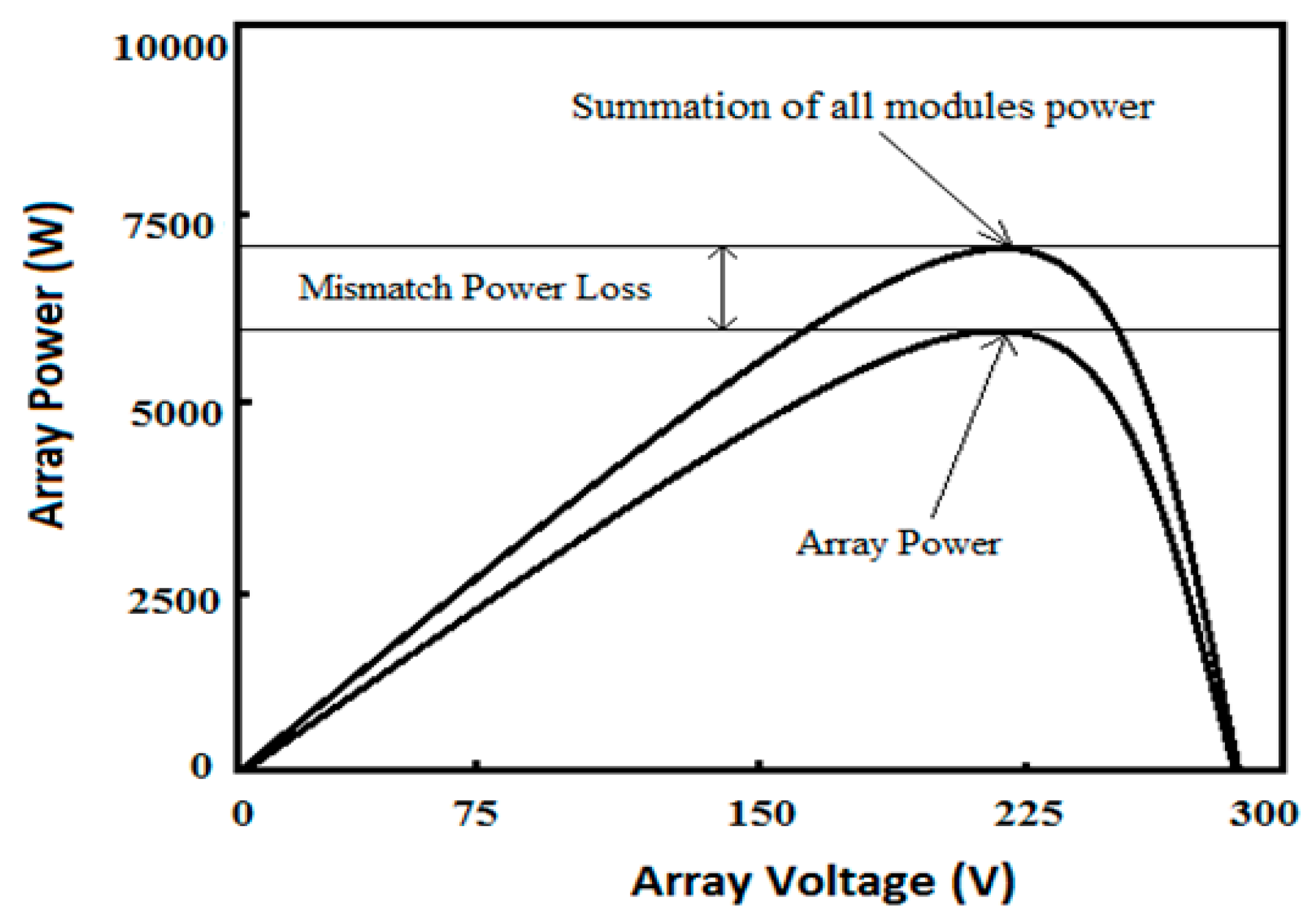
Mismatch losses are the performance penalty that accumulates when panels or strings in an array are not electrically identical, and in a series-parallel configuration the consequences of mismatch are more complex than in a purely series or purely parallel array because the mismatch affects both the voltage and current operating points simultaneously.
In a series string, mismatch between panels manifests as a current constraint. The panel with the lowest Isc sets the operating current for the entire string, and every other panel in the string operates below its maximum power point current. The power lost to current mismatch in a well-matched string of panels from the same manufacturing batch is typically 1 to 2 percent. In a string with mixed panel models, aged panels alongside new panels, or panels with different tilt angles, current mismatch losses can reach 5 to 10 percent of string output.
In a series-parallel array where multiple strings are connected in parallel at a combiner, voltage mismatch between strings is the additional failure mode. When two strings have different Vmp values at the operating point, whether from different panel counts, different panel models, different levels of soiling, or different tilt and orientation, the combiner forces both strings to operate at a compromise voltage that is optimal for neither. The string with the higher natural Vmp is pushed below its maximum power point. The string with the lower natural Vmp is pushed above its maximum power point. Both strings deliver less power than they would if each were connected to its own independent MPPT input.
The design rules that prevent significant mismatch losses in series-parallel arrays are straightforward and must be treated as non-negotiable constraints:
Series-Parallel Mismatch Prevention Rules:
All strings must have identical panel count per string
All strings must use the same panel model and vintage
All strings must have the same tilt angle and azimuth orientation
All strings must have the same cable length from array to combiner
Differently oriented groups -> connect each to a separate MPPT input
When site constraints make identical string configuration impossible, for example when panels are split across two roof faces with different orientations, the correct engineering response is to connect each differently oriented group to a separate MPPT input rather than combining them at a single combiner. Most modern hybrid inverters and quality standalone MPPT controllers offer dual MPPT inputs precisely for this reason, and using them correctly eliminates orientation mismatch losses entirely.
Module-Level Power Electronics for Complex Shading Profiles
Everything covered in the previous eight sections assumes a conventional string architecture where panels are connected in series and parallel combinations feeding a single MPPT input per string group. That architecture is the correct default for the vast majority of off-grid installations, and its limitations only become genuinely binding when the installation site has a shading profile that is too complex and too persistent to be managed through careful string design alone. When that threshold is crossed, module-level power electronics become the engineering tool of choice.
The relevant technology for off-grid DC-coupled systems is the DC optimizer, not the microinverter. Microinverters convert DC panel output to AC at the panel itself, which makes them incompatible with a DC-coupled battery system. DC optimizers are panel-level DC-to-DC converters that perform maximum power point tracking independently for each panel and output a regulated voltage to the string, allowing the MPPT charge controller to see a consistent, well-conditioned DC input regardless of what shading conditions individual panels are experiencing.
The string shading penalty described in Section 3, where a single shaded panel limits the output of its neighbors through the current bottleneck effect, is eliminated entirely when DC optimizers are fitted because each panel’s MPPT operation is decoupled from every other panel in the string.
The case for specifying DC optimizers is strongest when the installation has a complex shading profile from fixed objects, specifically trees, chimneys, vent pipes, adjacent structures, or roof penetrations that cast narrow, consistent shadows across individual panels or cell rows at predictable times of day. On a site where shading is intermittent, brief, or affects entire strings simultaneously rather than individual panels, the production improvement from DC optimizers is too small to justify the additional component cost and system complexity.
The cost-benefit threshold I apply is as follows. If a shading analysis using PVGIS or equivalent software shows that shading-related losses exceed 8 to 10 percent of annual array output under a conventional string architecture, DC optimizers are worth evaluating on their economic merits. Below that threshold, careful string design, string reorientation away from shaded zones, and acceptance of the residual shading loss is the more cost-effective approach. Above that threshold, the optimizer investment typically recovers its cost within 3 to 5 years through improved energy harvest, particularly on sites with LiFePO4 battery systems where the improved daily charging consistency reduces battery cycling stress and extends service life.
Conclusion
String configuration is one of those design decisions that looks simple on the surface and reveals its complexity only when you work through all of the constraints it must satisfy simultaneously. Series wiring, parallel wiring, and series-parallel combinations are not interchangeable options that produce different aesthetics with similar results. They are distinct electrical topologies with different operating characteristics, different cable sizing requirements, different shading behavior, and different controller compliance profiles that must each be verified independently before a configuration is accepted.
The decision framework that emerges from this post is straightforward to apply once the site conditions are known. Series wiring is the default for long cable runs and unshaded sites because it minimizes resistive losses and keeps array current within the MPPT controller’s optimal operating range. Parallel wiring is justified on short cable runs with persistent partial shading that affects individual panels rather than entire strings, accepting the higher current and the cable sizing penalty that comes with it. Series-parallel is the topology for larger arrays where both voltage and current targets must be met simultaneously, with the additional requirement that all strings in the parallel combination must be electrically identical to avoid mismatch losses at the combiner.
Two compliance checks are mandatory for every series string configuration before commissioning: the cold morning Voc check that confirms the string will not damage the controller at minimum temperature, and the hot afternoon Vmp check that confirms the string will maintain MPPT lock at maximum cell temperature. Both must pass. A string that satisfies one and fails the other is not a valid configuration regardless of how clean the rest of the design is.
In the next post in this series we will move into MPPT charge controller selection in detail, covering exactly how MPPT tracking works, what the controller specifications mean in practice, and how to match controller capacity to the array and battery system you have designed.
For the array sizing methodology that string configuration feeds into, refer to our engineering guide on how to size a solar array for an off-grid lithium battery system and our pillar post on designing an off-grid power system using lithium batteries.

Hi, i am Engr. Ubokobong a solar specialist and lithium battery systems engineer, with over five years of practical experience designing, assembling, and analyzing lithium battery packs for solar and energy storage applications, and installation. His interests center on cell architecture, BMS behavior, system reliability, of lithium batteries in off-grid and high-demand environments.