Introduction
Charge and discharge cycle ratings are frequently presented as a single headline metric for lithium battery lifespan, yet in practice they represent only a narrow abstraction of a much more complex degradation process. Cycle life figures quoted in datasheets are derived under tightly controlled laboratory conditions, often assuming fixed temperature, limited depth of discharge, moderate C-rates, and carefully defined voltage cut-off thresholds. When these assumptions are violated, as they often are in real-world energy storage systems the relevance of the quoted cycle number rapidly diminishes.
Lithium battery degradation during cycling is driven by a combination of electrochemical, thermal, and mechanical mechanisms. Each charge and discharge event contributes incrementally to capacity fade and internal resistance growth through processes such as solid electrolyte interphase (SEI) layer evolution, lithium inventory loss, electrode material fatigue, and, under adverse conditions, lithium plating. Importantly, the rate at which these mechanisms progress is highly sensitive to operating parameters including depth of discharge (DoD), charge and discharge C-rates, absolute voltage window, and cell temperature.
In practical battery pack deployments, particularly in solar-inverter and backup power systems, cells are rarely cycled uniformly. Variations in impedance, thermal gradients, and load distribution cause certain cells to experience higher stress, leading to imbalance and accelerated local degradation. As a result, system-level failure often occurs well before the theoretical end-of-life of individual cells, underscoring the importance of charge control, balancing strategies, and protection logic implemented by the Battery Management System (BMS).
This article provides a system-level analysis of charge and discharge cycles in lithium battery packs. It examines what constitutes a cycle in engineering terms, how cycling parameters influence dominant degradation pathways, and why cycle count alone is an insufficient predictor of usable battery lifespan. The discussion is framed around real operating conditions rather than idealized laboratory assumptions, with emphasis on how informed control of voltage, current, temperature, and state-of-charge windows can significantly extend practical service life.
What is a Charge/Discharge Cycle
In engineering practice, a charge/discharge cycle is not strictly defined as a transition from 0% state of charge (SOC) to 100% SOC and back. Instead, cycle life is measured using the concept of Equivalent Full Cycles (EFCs), which represents the cumulative charge throughput normalized to the nominal capacity of the cell or battery pack.
An equivalent full cycle occurs when the total charge removed from and returned to the battery equals 100% of its rated capacity, regardless of how that energy transfer is distributed across multiple partial cycles. For example, two 50% depth-of-discharge (DoD) cycles, four 25% cycles, or ten 10% cycles are all electrically equivalent to one full cycle from a charge throughput perspective.
Mathematically, equivalent full cycles can be expressed as:

where Qdischarged is the cumulative discharged capacity over time, and Qnominal is the rated capacity of the battery. This formulation highlights that cycle count is fundamentally an energy throughput metric, not a behavioral one.
However, while EFCs provide a convenient normalization method, they do not capture the nonlinear relationship between degradation and operating conditions. A single 100% DoD cycle induces significantly more structural and electrochemical stress than multiple shallow cycles summing to the same energy throughput. This is because degradation mechanisms such as SEI growth, particle cracking, and electrolyte decomposition do not scale linearly with charge throughput.
In practical lithium battery systems, especially those used in solar energy storage and inverter applications, batteries are often subjected to partial cycling with irregular SOC swing amplitudes. Daytime charging, evening discharge, intermittent high-load events, and standby periods produce cycling profiles that differ substantially from standardized test protocols. As a result, two systems experiencing the same number of equivalent full cycles may exhibit markedly different capacity fade trajectories depending on their SOC operating window and current profiles.
This distinction is critical when interpreting manufacturer cycle-life specifications. Datasheet values typically assume a fixed DoD (commonly 80% or 100%), constant current charge and discharge rates, and stable temperature. When real-world systems deviate from these assumptions, cycle count alone becomes an incomplete predictor of usable life. Understanding how cycles are accumulated, and under what conditions is therefore more important than the absolute number of cycles recorded.
Why is Lithium Battery Cycle Life Not a Single Fixed Number?
Lithium battery cycle life cannot be accurately described by a single universal number. It is highly dependent on operating conditions, cell chemistry, and system management. Cycle life is best understood as a conditional metric: the number of charge and discharge events a battery can sustain before reaching a defined end-of-life capacity, typically 80% of nominal capacity rather than complete failure. This distinction is critical for system designers and engineers when comparing cells or designing packs for real-world use.
Influence of Operating Conditions
Even within the same chemistry, realized cycle life can vary dramatically depending on how the battery is used:
- Depth of Discharge (DoD): Shallow cycling (e.g., 10–30% DoD) can extend practical cycle life far beyond deep-cycle operation, since electrochemical and mechanical stresses scale nonlinearly with SOC swing.
- Charge and Discharge C-Rates: High C-rate operation accelerates side reactions, increases heat generation, and raises the risk of lithium plating or electrode cracking.
- Voltage Window: Operating near maximum or minimum cell voltage significantly accelerates degradation. For example, repeatedly charging NMC cells to 4.2–4.3 V promotes SEI growth and electrolyte oxidation compared to a more conservative 4.0–4.1 V upper limit.
- Temperature: Elevated temperatures (>40 °C) accelerate chemical side reactions, while low temperatures increase internal resistance and increase the likelihood of lithium plating during charging.
Because of these factors, two batteries with identical chemistry and nominal capacity can experience vastly different lifespans under different operating regimes.
Typical Cycle Ranges for Common Lithium Chemistries
Different lithium chemistries exhibit well-known trade-offs between energy density and cycle life:
| Chemistry | Typical Cycle Life (80% Capacity) | Notes |
| LiFePO₄ (LFP) | 2000–5000 cycles | Excellent thermal stability and long cycle life; lower energy density |
| NMC (LiNiMnCoO₂) | 1000–2000 cycles | Higher energy density; sensitive to high voltage and temperature |
| LCO (LiCoO₂) | 500–1000 cycles | Common in portable electronics; limited lifespan for high-power use |
| NCA (LiNiCoAlO₂) | 1000–2000 cycles | High energy density for EVs; requires careful thermal management |
These ranges assume moderate DoD, typical C-rates, and test temperatures around 25 °C. Deviating from these conditions particularly by increasing DoD, temperature, or C-rate can reduce cycle life by 20–50% or more.
Why Manufacturers Rate Cycle Life to 80% Capacity
Manufacturers define battery end-of-life at 80% of nominal capacity for several practical reasons:
- Usability: Below this threshold, the battery often no longer delivers sufficient energy or power for its intended application.
- Nonlinear Aging: Capacity loss tends to accelerate as batteries age, and degradation beyond 80% can progress rapidly.
- Standardization: Using 80% capacity provides a consistent benchmark that allows meaningful comparison across chemistries and test protocols.
Understanding that cycle life is a conditional and relative measure not a simple count of “charges” is essential for designing reliable systems, setting appropriate operating limits, and selecting the right battery chemistry for a given application.
What Actually Degrades a Lithium Battery During Cycling?
Lithium battery degradation during charge and discharge cycling is not caused by a single failure mechanism but by the cumulative interaction of electrochemical side reactions, mechanical stress, and thermal effects. These mechanisms operate simultaneously and often reinforce one another, which is why degradation tends to accelerate with age rather than progress linearly.
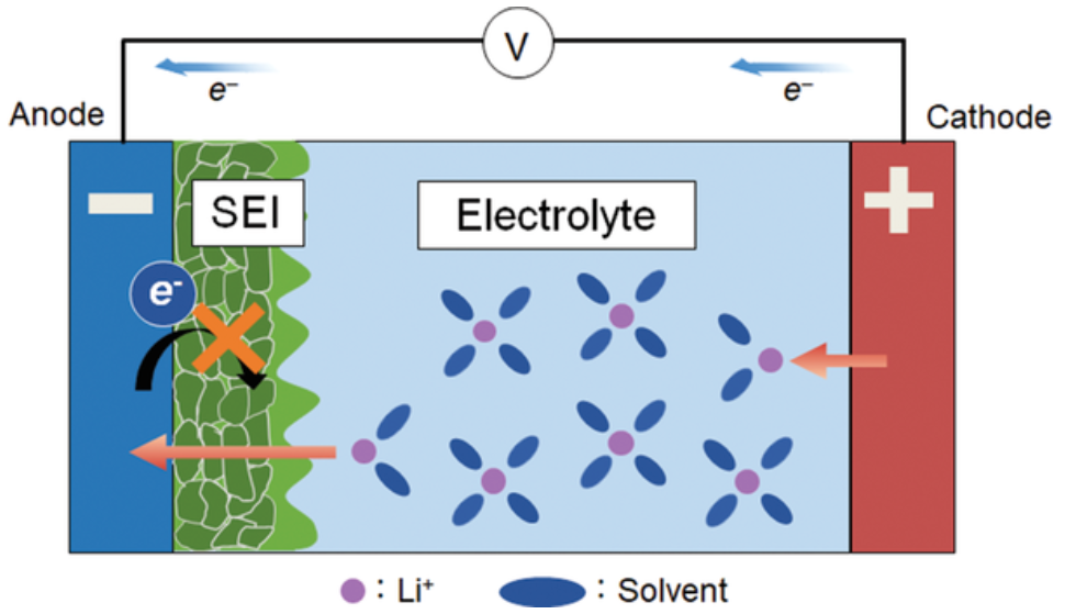
1.SEI Layer Growth and Internal Resistance Increase
One of the most important degradation mechanisms is the growth of the solid electrolyte interphase (SEI) layer. The SEI forms naturally on the anode during the first few charge cycles as the electrolyte decomposes and reacts with the electrode surface. Initially, this layer is beneficial because it stabilizes the electrode and prevents further electrolyte breakdown.
However, the SEI does not remain static. With continued cycling, high temperatures, or high voltages(overcharge), the layer thickens. Each time it grows, it consumes small amounts of lithium that can no longer participate in charging and discharging. As a result, the battery loses usable capacity. At the same time, a thicker SEI increases internal resistance, reducing power output and generating more heat during operation further accelerating degradation.
Key Takeaway:
Capacity fade is not the only aging metric that matters impedance growth often limits usable battery life before capacity loss becomes critical, particularly in high-power systems.
2.Lithium Plating During Fast or Cold Charging
Lithium plating occurs when lithium ions are reduced to metallic lithium on the anode surface instead of being properly intercalated into the graphite structure. This phenomenon is most likely under:
- High charge C-rates
- Low-temperature charging
- High SOC operation near upper voltage limits
Plated lithium reduces the amount of cyclable lithium and can form dendritic structures that pose safety risks. Even when dendrites do not cause internal short circuits, plated lithium often becomes electrochemically inactive, permanently reducing capacity.
From a system perspective, lithium plating is particularly dangerous because it may not be immediately visible through capacity measurements. Early indicators are often increased internal resistance and abnormal voltage behavior during charging.
Engineer’s Advice:
Fast charging should be dynamically limited at low temperatures and high SOC levels. Fixed charge-current limits are insufficient for long-term health preservation.
3.Mechanical Stress from Expansion and Contraction
Lithium-ion electrodes undergo repeated volumetric changes during cycling as lithium ions are inserted and removed. Over hundreds or thousands of cycles, this expansion and contraction causes:
- Micro-cracking of active material particles
- Loss of electrical contact within the electrode matrix
- Progressive reduction in active surface area
These mechanical effects are exacerbated by deep cycling and high current operation. Once cracks form, electrolyte penetration increases, exposing fresh surfaces and triggering additional SEI formation further accelerating degradation.
Why Does Battery Degradation Accelerates Over Time?
Battery degradation is inherently nonlinear. Early in life, cells experience relatively slow capacity fade and resistance increase. As degradation mechanisms compound, the rate of deterioration increases due to:
- Higher internal resistance causing more heat generation
- Increased localized current density in degraded regions
- Greater susceptibility to lithium plating and electrolyte breakdown
This explains why batteries often appear stable for a long period before experiencing a rapid decline in performance toward end-of-life.
Lithium battery aging is driven less by the number of cycles completed and more by how those cycles are executed specifically in terms of voltage, current, temperature, and depth of discharge.
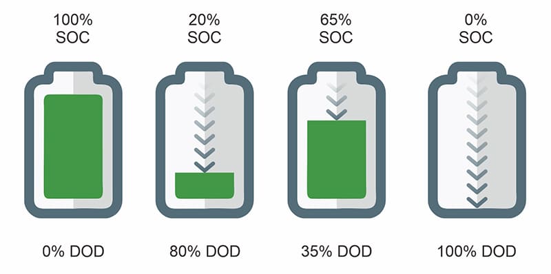
Depth of Discharge (DoD)
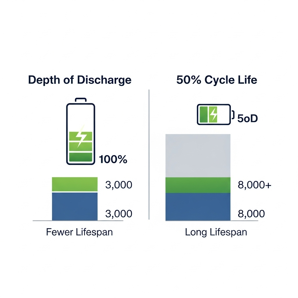
Depth of discharge describes the fraction of a battery’s total capacity that is removed during a charge–discharge event. A 100% DoD cycle corresponds to discharging the battery from full charge to its lower voltage limit, whereas a 20% DoD cycle uses only a small portion of the available capacity before recharging. Although these cycles may be electrically equivalent when summed over time, they are not equivalent from a degradation perspective.
Full-depth cycling imposes the highest electrochemical and mechanical stress on lithium-ion cells. At high and low states of charge, electrode materials operate closer to their structural and thermodynamic limits, increasing susceptibility to particle cracking, electrolyte oxidation, and accelerated SEI growth. Repeated exposure to these extremes compounds damage, even if the total energy throughput remains comparable to that of shallower cycling patterns.
By contrast, shallow cycling confines operation to a narrower and more stable SOC window, where electrode reactions are more reversible and side reactions progress more slowly. Empirical testing across multiple lithium chemistries consistently shows that reducing DoD significantly increases the total number of cycles a battery can deliver before reaching end-of-life. Operating within a mid-range SOC window commonly around 20–80% avoids the most aggressive voltage regions while preserving a large fraction of usable energy.
This behavior explains an apparent contradiction often observed in practice: batteries subjected to shallow daily cycling frequently outlast batteries that experience fewer but deeper cycles, even when both deliver similar cumulative energy over their lifetimes. The reason lies in the nonlinear relationship between degradation and SOC swing. Damage per cycle increases disproportionately as DoD increases, meaning that energy extracted at the extremes of SOC carries a higher aging penalty.
From a system perspective, this shifts the focus away from simple cycle counting toward energy throughput weighted by operating conditions. A battery that delivers 5,000 shallow cycles at moderate SOC may process more total energy over its life than one rated for 2,000 full cycles, while retaining lower internal resistance and better power capability. This distinction is particularly relevant in solar energy storage systems, where daily cycling profiles can be shaped through charge control, load scheduling, and reserve capacity settings.
Depth of discharge is one of the most powerful levers available to system designers and operators for extending lithium battery lifespan. Unlike cell chemistry, which is fixed at purchase, DoD is a controllable variable. Thoughtful management of SOC windows allows significant life extension without changes to hardware, purely through operational strategy.
Charge and Discharge Rates (C-Rates)
C-rate defines the rate at which a battery is charged or discharged relative to its nominal capacity and provides a normalized way to describe current stress independent of battery size. A charge and discharge rate of 1C implies that the battery is delivering its rated capacity over one hour, while lower or higher C-rates correspond to proportionally slower or faster energy transfer.

From a degradation standpoint, C-rate governs how aggressively electrochemical reactions are driven inside the cell. Higher currents increase polarization losses, raise internal temperature, and amplify concentration gradients within the electrodes and electrolyte. These effects occur during both charging and discharging, although the dominant failure mechanisms differ between the two.
During charging, elevated C-rates reduce the time available for lithium ions to diffuse and intercalate into the anode structure. When diffusion becomes rate-limiting particularly at low temperatures or high states of charge lithium plating can occur, permanently removing active lithium from the system. This makes charge C-rate one of the most sensitive parameters for long-term battery health.
During charge and discharging, high C-rates primarily manifest as increased voltage sag and resistive heating. As internal resistance rises with age, the same discharge current produces progressively higher heat generation, accelerating electrolyte degradation and mechanical fatigue of electrode materials. In high-power inverter systems, repeated high-current discharge events can therefore drive aging even if average depth of discharge remains moderate.
An important implication is that battery aging is influenced not only by how much energy is cycled, but also by how quickly that energy is transferred. Two systems delivering the same daily energy can experience very different degradation trajectories if one operates at sustained low C-rates while the other is subjected to frequent high-current transients. This effect is often underestimated in system designs that prioritize peak power capability without accounting for long-term thermal and electrochemical stress.
Because C-rate interacts strongly with temperature, voltage, and state of charge, its impact cannot be evaluated in isolation. Conservative current limits at high SOC, adaptive current reduction at low temperatures, and load smoothing strategies all play a role in moderating current-induced aging. In practice, systems that maintain moderate discharge rates and avoid aggressive charging currents tend to retain lower internal resistance and more stable performance over extended service life.
Voltage Limits: More Capacity Versus Longer Battery Life
Cell voltage is one of the most direct indicators of electrochemical state within a lithium battery and one of the strongest levers influencing degradation rate. While higher voltage operation increases usable capacity and energy density, it also accelerates several aging mechanisms. The choice of voltage limits therefore represents a fundamental trade-off between short-term performance and long-term lifespan.
Upper Cut-Off Voltage and Degradation Trade-Offs
At high states of charge, lithium-ion cells operate closer to their electrochemical stability limits. Increasing the upper cut-off voltage increases the amount of lithium extracted from the cathode and inserted into the anode, raising the apparent capacity. However, this comes at the cost of elevated electrode potential, which accelerates electrolyte oxidation at the cathode and intensifies SEI growth at the anode.
For common NMC-based cells, charging to 4.2 V already represents a compromise between capacity and longevity. Pushing the upper limit to 4.25 V or 4.3 V may deliver a modest capacity increase, but the resulting increase in parasitic reactions can disproportionately shorten cycle life. The degradation penalty grows nonlinearly as the voltage approaches the upper stability limit of the electrolyte.
Why Charging to 100% Every Time Is Harmful
Charging to 100% state of charge corresponds to operating at the highest allowable cell voltage for a given chemistry. Remaining at this voltage even without active cycling accelerates calendar aging through continuous electrolyte decomposition and SEI thickening. When combined with elevated temperature or high charge currents, the risk of lithium plating increases further.
In practical systems, this means that a battery held at full charge for extended periods can age faster than one that is cycled regularly but maintained within a moderate SOC window. The effect is especially pronounced in backup and solar storage systems where batteries may sit fully charged for long durations.
This is why devices that remain plugged in at full charge such as laptops or phones often experience noticeable capacity loss over time. The issue is not the charger itself, but the prolonged exposure to high voltage. Repeatedly charging to 100% compounds this effect, especially when combined with elevated temperatures.
Reduced Voltage Limits and Lifespan Extension
Lowering the upper cut-off voltage by even a small margin can significantly reduce aging rates. Reducing the maximum charge voltage by 50–100 mV decreases electrode stress and slows the growth of resistive layers, often extending usable cycle life by a substantial margin while sacrificing only a small fraction of nominal capacity.
This is supported by industry data from Battery University, which notes that for most lithium-ion batteries, every 0.10V reduction in peak charge voltage can double the cycle life, though it comes with a proportional reduction in usable capacity
From a system design perspective, this trade-off is often favorable. The marginal energy gained by charging to absolute maximum voltage is frequently outweighed by the long-term losses associated with faster degradation, increased internal resistance, and reduced power capability. This is why many long-life energy storage systems deliberately operate below the maximum rated voltage, prioritizing stability and longevity over peak capacity.
Ultimately, voltage limits act as a unifying control variable that influences charge behavior, discharge performance, and aging kinetics simultaneously. Thoughtful selection of upper and lower voltage thresholds allows system designers to shape battery behavior in a way that aligns with the intended duty cycle, whether the goal is maximum energy density or extended service life.
Many battery management systems take advantage of this by reserving a portion of the battery’s true capacity as a buffer. In electric vehicles, this strategy allows manufacturers to advertise long battery lifetimes while still delivering consistent real-world performance. The result is a battery that delivers less peak capacity per charge, but far more total energy over its usable life
Temperature
Temperature plays a central role in lithium battery aging because it directly influences reaction kinetics, transport processes, and material stability. Unlike depth of discharge, C-rate, or voltage each of which can be controlled through electrical design temperature acts as a global stressor that amplifies the impact of all other operating conditions. As a result, thermal effects often dominate real-world degradation behavior.
High-Temperature Effects During Charge and Discharge
At elevated temperatures, chemical reaction rates within the cell increase exponentially. This accelerates electrolyte decomposition, SEI growth, and transition-metal dissolution from the cathode, all of which contribute to capacity fade and rising internal resistance. During charging, high temperature exacerbates side reactions at high voltage, while during discharging it increases resistive losses and heat generation, creating a reinforcing thermal feedback loop.
Sustained high-temperature operation is particularly damaging because it affects both cycle aging and calendar aging simultaneously. Even in the absence of heavy cycling, prolonged exposure to elevated temperature can significantly reduce usable life by consuming active lithium and degrading electrode interfaces.
Cold-Temperature Charging Risks
Low temperatures introduce a different set of challenges. As temperature decreases, lithium-ion diffusion slows and internal resistance rises. During charging, this can cause lithium ions to accumulate at the anode surface faster than they can intercalate, increasing the likelihood of lithium plating. Unlike many high-temperature degradation processes, lithium plating can occur rapidly and cause irreversible damage in a relatively small number of charge events.
The risk is highest when cold charging is combined with high charge currents or high states of charge. While discharge at low temperature primarily results in reduced power capability and voltage sag, charging under the same conditions poses a more serious threat to long-term health.
Thermal Management as a System-Level Requirement
Because temperature interacts with voltage, current, and state of charge, thermal management cannot be treated as a secondary consideration. Uneven temperature distribution within a battery pack leads to non-uniform aging, as warmer cells degrade faster and drift out of balance. This imbalance further increases stress on the remaining cells, accelerating overall pack degradation.
Effective thermal management encompasses more than cooling alone. It includes appropriate cell spacing, airflow design, heat sinking, controlled charging at low temperatures, and operating strategies that avoid prolonged exposure to thermal extremes. In many systems, modest improvements in temperature control deliver greater lifespan benefits than increasing cell capacity or nominal cycle rating.
Ultimately, temperature sets the context in which all other aging mechanisms operate. Batteries subjected to moderate voltage, current, and depth of discharge can still experience rapid degradation if thermal conditions are poorly managed, while well-controlled thermal environments allow lithium batteries to operate closer to their optimal performance envelope for much longer periods.
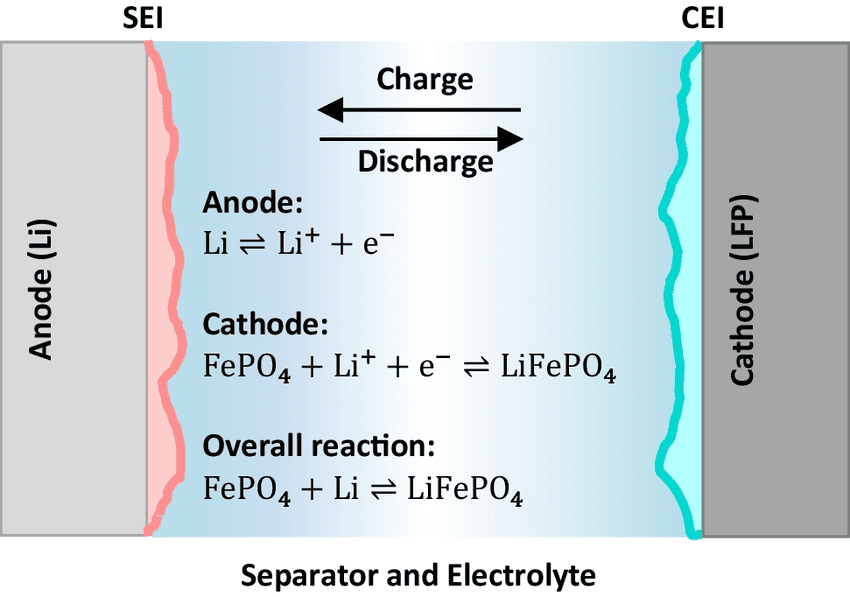
Cycle Aging vs Calendar Aging
Lithium batteries degrade through two fundamentally different processes: cycle aging, which occurs due to repeated charge and discharge events, and calendar aging, which happens over time even if the battery is not actively cycled. Both contribute to capacity loss and rising internal resistance, but their relative importance depends on usage patterns, environmental conditions, and system design.
Why Does Batteries Degrade Even When Not Used?
Calendar aging is driven primarily by chemical side reactions that continue in the absence of cycling. These include SEI layer thickening, electrolyte decomposition, and slow transition-metal dissolution from the cathode. The rate of calendar aging is strongly influenced by state of charge and temperature: batteries stored at high SOC and elevated temperatures age disproportionately faster than those stored at moderate SOC or cooler conditions. Even a battery sitting on a shelf or in a fully charged solar storage system is not immune to these processes.
Which Aging Mechanism Dominates in Solar Systems
In real-world solar installations, both mechanisms interact, but the dominant aging mode depends on system design:
- Daily cycling systems (e.g., residential solar storage with moderate DoD) tend to experience cycle aging as the primary driver of degradation. Repeated charging from solar input and daily discharging to supply loads contributes to SEI growth, mechanical fatigue, and capacity fade over thousands of cycles.
- Backup or float-charged systems, which remain fully charged for extended periods with infrequent use, are more affected by calendar aging. Prolonged high SOC storage accelerates chemical side reactions, leading to capacity loss even if the battery is rarely discharged.
This distinction explains why two batteries with identical chemistry and cycle ratings can have dramatically different service lives depending on usage patterns. In solar-plus-storage systems, calendar aging can often match or exceed cycle aging if thermal and SOC conditions are not carefully managed.
Implications for Backup vs Daily-Use Batteries
Understanding the relative contributions of cycle and calendar aging is critical for system specification:
- Daily-use systems benefit from operating in moderate SOC windows, limiting DoD and C-rates, and maintaining thermal control to extend cycle life.
- Backup systems gain more from storing batteries at lower SOC, applying periodic equalization or refresh cycles, and minimizing temperature extremes to slow calendar aging.
Ultimately, battery lifespan is the result of both the number and the nature of cycles, as well as the time spent at high stress conditions even when idle. Designing for the intended duty profile whether daily cycling or standby is essential to maximize usable life and avoid unexpected early degradation.
Why Battery Packs Fail Before Individual Cells Do
Even when individual cells are high-quality and exhibit long cycle life, the overall battery pack often reaches end-of-life earlier. This discrepancy arises because packs are more than just a sum of their cells they are complex systems in which imbalance, thermal gradients, and protection strategies play a critical role.
Also Read: The Lithium Battery Architecture Handbook: A Systems Guide to Cells, BMS, and Internal Engineering
1.Cell Imbalance and the Weakest-Cell Effect
No two lithium cells are perfectly identical. Small variations in capacity, internal resistance, or thermal behavior accumulate over time. During cycling, these differences manifest as cell imbalance, where some cells reach voltage or SOC limits faster than others. Because the pack is constrained by the most stressed cell, the “weakest-cell effect” determines the usable pack capacity. Once the weakest cell reaches its operational limits, charging or discharging must be curtailed to prevent overvoltage, undervoltage, or thermal stress, effectively limiting the pack’s usable energy well before the stronger cells degrade.
2.Importance of Balancing and Protection
Balancing circuits, whether passive or active, play a vital role in mitigating the weakest-cell effect. By equalizing SOC across cells, they reduce the likelihood of overcharging or deep discharging individual cells, thereby prolonging pack life. Similarly, protective features such as overvoltage, undervoltage, overcurrent, and thermal cutoffs safeguard the pack from extreme conditions. Even with perfect cells, a lack of proper balancing and protection results in accelerated localized degradation, creating hotspots of stress that limit overall pack performance.
How Poor BMS Design Shortens Pack Life
A poorly designed Battery Management System (BMS) exacerbates these effects. Slow or ineffective balancing allows minor mismatches to grow into critical imbalances. Inadequate thermal monitoring can hide dangerous hotspots. Improper current limits can push cells into conditions that accelerate SEI growth or lithium plating. In short, the BMS governs how real-world operating stresses translate into degradation, and a weak BMS can turn otherwise reliable cells into a pack that fails prematurely.
System-level design considerations must therefore go beyond choosing high-quality cells. Effective pack design includes careful cell matching, robust balancing strategies, precise thermal management, and intelligent protection logic. These factors collectively determine the usable life of a battery pack, often more than the nominal ratings of the individual cells themselves.
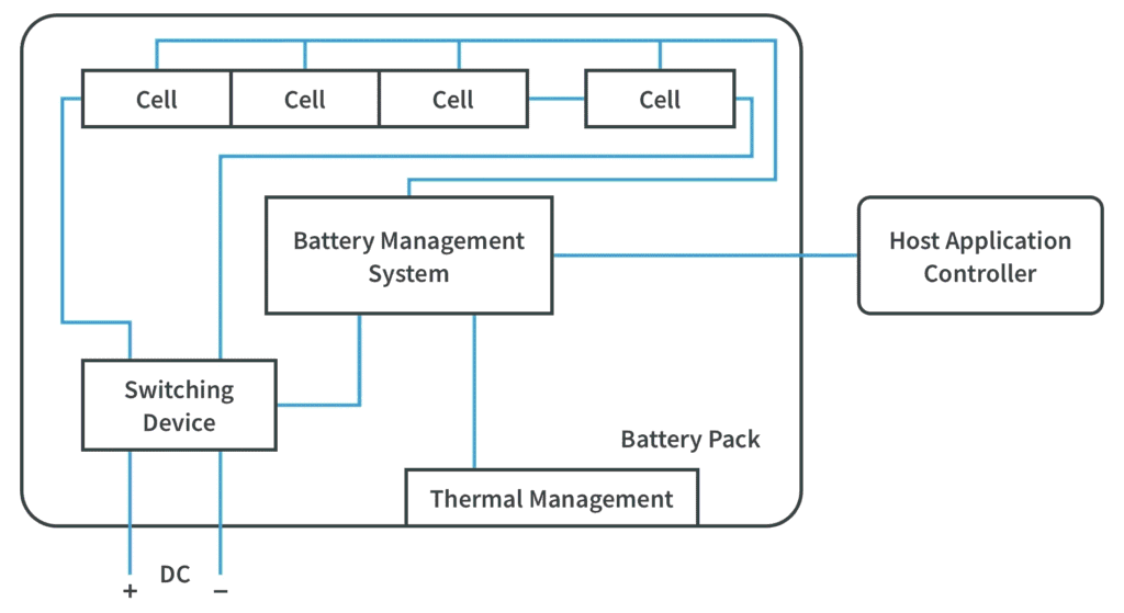
The Role of the BMS in Extending Cycle Life
The Battery Management System (BMS) serves as the central control hub for lithium battery packs, coordinating charging, discharging, and protection to preserve both safety and long-term performance. A well-designed BMS directly influences cycle life by managing stressors that cause degradation at the cell and pack level.
1.Charge/Discharge Current Control
The BMS regulates current flow to prevent excessive charge or discharge rates, which are major contributors to chemical, thermal, and mechanical stress. During charging, the BMS limits current to avoid lithium plating and excessive SEI growth, particularly at low temperatures or high SOC. During discharging, it prevents overcurrent conditions that can produce voltage sag, heat, and accelerated electrode fatigue. By dynamically adjusting current limits according to temperature, SOC, and cell condition, the BMS ensures that each cycle imposes only tolerable stress, thereby extending usable life.
2.SOC Window Enforcement
State-of-charge management is another key function. By maintaining cells within a defined SOC window avoiding extremes at both the top and bottom of their voltage range the BMS reduces the disproportionate degradation associated with high DoD or repeated full-charge operation. Mid-range cycling not only lowers chemical stress but also mitigates mechanical fatigue caused by repeated expansion and contraction of electrode materials.
3.Thermal and Voltage Protections
Temperature and voltage extremes accelerate nearly all degradation mechanisms. The BMS monitors individual cell temperatures and voltages, enabling protective actions such as load shedding, charge reduction, or fan control. Preventing localized hotspots and overvoltage events reduces SEI thickening, lithium plating, and electrolyte decomposition, all of which directly impact cycle life. Coordinated thermal and voltage management ensures that the pack ages uniformly, preventing the weakest-cell effect from prematurely limiting usable capacity.
Why Smart BMS Designs Matter
Not all BMS implementations are equal. “Smart” designs integrate adaptive current control, SOC-dependent limits, temperature compensation, and predictive alerts based on historical and real-time data. By treating the pack as a dynamic system rather than a static collection of cells, a smart BMS can maximize energy throughput while minimizing degradation. In practical terms, packs with intelligent BMS control often achieve significantly higher effective cycle counts and maintain better capacity retention than those relying on simple fixed-limit protection.
In short, the BMS does more than protect against catastrophic failure it actively shapes the operational environment to slow degradation. Optimizing BMS functions is therefore one of the most effective ways to extend battery pack life, even when using cells with modest cycle ratings.
The Engineers Practical Lifespan Tips for A Longer Lasting Battery
While the underlying science of lithium degradation can be complex, understanding a few operational principles allows users to maximize battery life without sacrificing everyday usability. These practices translate technical knowledge into actionable strategies for both solar storage and backup systems.
1.Ideal SOC Operating Window
Maintaining the battery within a moderate state-of-charge range is one of the most effective ways to extend cycle life. Operating between roughly 20–80% SOC avoids the voltage extremes that accelerate SEI growth, lithium plating, and mechanical stress. Shallow daily cycles within this window allow more total energy throughput over the battery’s life compared to frequent deep discharges, even if nominal capacity appears slightly reduced.
2.Charging Habits That Extend Life
Charging strategy is critical. Fast charging at high SOC or low temperatures should be minimized, while regular, controlled charging within the mid-SOC range reduces chemical stress. Where possible, avoid keeping batteries at 100% charge for extended periods, especially in warm environments. Slow, consistent charging aligned with system load can dramatically reduce cumulative aging effects.
3.Environmental and Installation Considerations
Temperature management is central to real-world longevity. Batteries should be installed in locations with stable, moderate temperatures and protected from direct sunlight or heat sources. For systems exposed to variable climates, active thermal control, proper ventilation, and insulation can prevent both localized overheating and cold-related charging issues. Even modest improvements in temperature stability often deliver larger lifespan gains than incremental increases in cycle rating or capacity.
4.When to Prioritize Lifespan Over Capacity
In applications where longevity is critical such as backup systems or daily solar storage intended to last a decade accepting slightly lower usable capacity in exchange for gentler operating conditions is often the optimal strategy. This may involve limiting upper voltage cutoffs, reducing maximum charge and discharge currents, or keeping the SOC window conservative. In contrast, high-energy-density operation may be justified when peak capacity is more important than long-term durability.
By applying these principles consistently, users can maintain reliable performance, reduce maintenance costs, and extract the maximum service life from lithium battery packs. Thoughtful operation, rather than simply choosing high-rated cells, often has the greatest impact on real-world longevity.
Common Myths About Lithium Battery Cycles
Lithium-ion batteries are often discussed using simplified rules of thumb that sound reasonable but are technically incomplete or misleading. These myths persist because battery behavior is not intuitive, and because marketing language often prioritizes convenience over longevity. Separating myth from reality is key to using batteries intelligently.
Myth 1: “Always Charge to 100%”
Reality: Charging to the absolute maximum voltage for every cycle is one of the fastest ways to accelerate degradation. High SOC increases SEI growth, electrolyte decomposition, and lithium plating risk. Occasional full charges may be acceptable for capacity calibration, but daily operation is best limited to a moderate SOC window typically 20–80% for most lithium chemistries. This approach preserves both cycle life and power capability without substantially reducing usable energy.
Myth 2: “More Cycles Means Better Battery”
Reality: Cycle count alone does not define battery quality or lifespan. Not all cycles are equal a shallow, moderate SOC cycle is far less stressful than a deep, high-current cycle. A battery with fewer deep cycles can age faster than one with many shallow cycles, even if the total energy throughput is similar. What matters is how the cycles are executed, including DoD, C-rate, and operating temperature.
Myth 3: “Fast Charging Doesn’t Matter”
Reality: High charge currents accelerate chemical degradation, especially at high SOC or low temperatures. Fast charging increases the risk of lithium plating on the anode, thickening of the SEI layer, and irreversible capacity loss. While modern lithium chemistries tolerate moderate fast charging, charge rate control is critical for longevity, particularly in multi-kilowatt solar storage or high-power applications.
Myth 4: “Aging Only Happens During Cycling”
Reality: Calendar aging is often underestimated. Even a battery left fully charged without use will degrade over time due to SEI growth, electrolyte breakdown, and temperature-dependent chemical reactions. Long-term storage at high SOC or elevated temperatures accelerates this effect, making calendar aging a dominant factor in standby or backup systems.
By understanding these myths and the realities behind them, users can avoid practices that accelerate wear and adopt operational strategies that maximize both lifespan and reliability. Misconceptions often lead to unnecessary stress on the battery, while informed operation leverages the full potential of modern lithium technology.
Conclusion
Lithium battery longevity is the product of multiple interacting factors: depth of discharge, charge and discharge rates, voltage limits, temperature, calendar aging, and the quality of pack management. While individual cell specifications provide a starting point, real-world lifespan is determined primarily by system-level decisions and operational discipline.
Key technical takeaways include:
- Moderate SOC windows dramatically extend cycle life, reducing chemical and mechanical stress.
- Charge and discharge current control prevents lithium plating, excessive heating, and mechanical fatigue.
- Voltage management particularly avoiding repeated full charges limits accelerated degradation at high SOC.
- Temperature control ensures that both cycling and calendar aging proceed at manageable rates, preventing hotspots and uneven pack wear.
- BMS intelligence is critical: balancing, protection, and adaptive control mitigate the weakest-cell effect and optimize pack performance.
Ultimately, buyers, installers, and system designers should prioritize operational strategy and pack-level management over chasing high cell specifications alone. A well-designed system that carefully manages SOC, current, and temperature will often outperform higher-rated cells subjected to poor operational practices.
For end users, this means embracing moderate charge habits, respecting C-rate and temperature limits, and investing in intelligent BMS solutions. These strategies do more to preserve battery life than any incremental increase in rated capacity, ensuring reliable performance and cost-effective longevity over the life of the system.
I am committed to uncovering the truth behind lithium and solar systems, separating fact from myth, and providing actionable, evidence-based guidance. This blog is just one part of that effort. By following these insights and staying connected, you’ll gain reliable strategies to extend battery life, optimize system performance, and avoid costly mistakes. Keep coming back as I continue to dive deeper into the realities of solar storage, battery management, and energy system design because understanding the science is the first step toward building systems that truly last.

Hi, i am Engr. Ubokobong a solar specialist and lithium battery systems engineer, with over five years of practical experience designing, assembling, and analyzing lithium battery packs for solar and energy storage applications, and installation. His interests center on cell architecture, BMS behavior, system reliability, of lithium batteries in off-grid and high-demand environments.