Introduction
Eighteen months after a residential off-grid system was commissioned and handed over, the client added a second air conditioner. The unit was installed by a different contractor who connected it to the existing distribution board, tested it on its own circuit, confirmed it cooled the room, and left. The system ran normally for three weeks.
Then on a hot afternoon in the second week of March, both air conditioners were running simultaneously with the refrigerator, the lighting, and a television. The inverter shut down on overload. The client called the original installer, who arrived the following morning, opened the Cerbo GX alarm log, and found that the combined peak simultaneous load at the moment of shutdown was 4,100W, 37 percent above the Multiplus-II 48/3000’s continuous rating and well above its surge rating with both compressors cycling through their startup sequences within seconds of each other.
No component had failed. The Multiplus-II had done exactly what it was designed to do: protect itself from a load it was not rated to serve. The problem was not the inverter. The problem was the expansion decision that had been made without checking the inverter’s remaining capacity headroom, without checking the surge implications of a second compressor load, and without checking whether the battery bank could sustain the increased daily energy demand through a two-day overcast period.
Every expansion decision on an existing off-grid system interacts with existing constraints. This post establishes the framework for analysing those constraints before any expansion component is purchased, and applies it to the cluster system through a complete worked expansion specification.
Off-Grid Solar System Expansion Constraint Analysis Framework
An off-grid system expansion is not an additive process. It is a redesign of the existing system within the constraints imposed by the components already installed. Every new load, every new panel, and every new battery string changes at least one parameter that the existing components were sized to handle, and the expansion is only valid if every affected component can accommodate the new parameter within its rated limits. The expansion constraint analysis is the process of identifying which parameters change, which components those parameters affect, and whether the affected components can handle the new values or must be upgraded.
The five constraints that every expansion must be checked against in sequence are as follows. The MPPT controller input voltage constraint limits the maximum string Voc the array can present to the controller’s input terminals. The MPPT controller output current constraint limits the maximum combined array output current the controller can deliver to the battery bank after derating. The inverter continuous and surge rating constraint limits the maximum peak simultaneous AC load the inverter can serve. The battery charge and discharge current constraint limits the maximum current the bank can accept during charging and deliver during discharge. The DC cable rating constraint limits the maximum current the existing cable runs can carry without exceeding their derated thermal limits.
| Constraint | Parameter to Check | Source Document |
| MPPT input voltage | String Voc at T_min vs 90% of controller rating | Post #7 Voc calculation |
| MPPT output current | Combined array output current vs derated 60A | Post #7 output current check |
| Inverter continuous | Peak simultaneous load vs 3,000VA rating | Post #9 load verification |
| Inverter surge | Peak load + inrush vs 5,500VA surge rating | Post #9 surge verification |
| Battery charge current | Combined MPPT output vs CCL from BMS | Post #12 CCL verification |
| DC cable rating | New circuit current vs cable derated rating | Post #10 thermal constraint |
The constraint analysis must be completed before any expansion component is purchased. Discovering a binding constraint after a new inverter has been delivered and the existing inverter has been decommissioned forces a choice between returning the new component, purchasing an additional upgrade, or operating the expanded system above its rated limits. None of these outcomes is acceptable on a professionally installed system, and all of them are prevented by completing the constraint analysis at the planning stage.
The commissioning documentation produced at handover per Post #13 is the primary reference for the existing component ratings. On installations where commissioning documentation was not produced, the cable cross-sections must be physically verified by inspection before any expansion that increases circuit currents. For the commissioning documentation requirements, refer to our engineering guide on system monitoring, commissioning, and fault diagnosis for off-grid solar systems.
Array Expansion
Array expansion is the most common expansion request on an established off-grid installation, and it interacts with the MPPT controller’s input voltage and output current constraints simultaneously. The three scenarios that cover the range of array expansion decisions are adding panels to existing strings, adding new parallel strings within the existing controller’s capacity, and adding a second MPPT controller when the existing controller’s capacity is exhausted.
Scenario 1: Adding Panels to an Existing String
Adding one panel to a 3S string produces a 4S string. The new string Voc must be recalculated at the minimum installation temperature and checked against 90 percent of the controller’s maximum input voltage:
Voc_cold_4S = 4 x 41V x (1 + (-0.0029 x (18 - 25)))

Voc_cold_4S = 4 x 41V x 1.0203 = 167.3V

90% of controller rating = 0.90 x 150V = 135V

167.3V > 135V -> FAIL — 4S string incompatible with SmartSolar MPPT 150/60

This is the most common array expansion error in the field: adding a panel to a string without recalculating the cold Voc. The 3S string was specified with a 25.5V voltage margin against the controller’s 90 percent limit. Adding one panel consumes that margin entirely and exceeds the limit by 32.3V. The only path to adding more panels on this controller is a third parallel string rather than a longer series string, or replacing the controller with one rated for a higher input voltage such as the Victron SmartSolar MPPT 250/60.
Scenario 2: Adding a New Parallel String
Adding a third 3S string to the existing 2-string array increases the combined array power from 2,400W to 3,600W. The new combined MPPT output current must be recalculated:
I_output_new = (P_array_new x derating) / V_battery
I_output_new = (3,600W x 0.718) / 48V = 2,584.8 / 48 = 53.8A

Derated controller output = 60A x (1 - 0.025 x (47 - 45)) = 60A x 0.95 = 57A

53.8A < 57A -> PASS — third string within controller capacity

The third string adds 12 percent more output current headroom to the controller before it clips. The new string requires a 15A solar string fuse at the combiner box input, and the combiner box must have a spare input terminal. If the existing combiner box is a two-input model, it must be replaced with a three-input model before the new string is connected. The combiner-to-MPPT cable carries 31.5A combined current from three strings, which must be rechecked against the two-constraint framework from Post #10 for the new combined current.
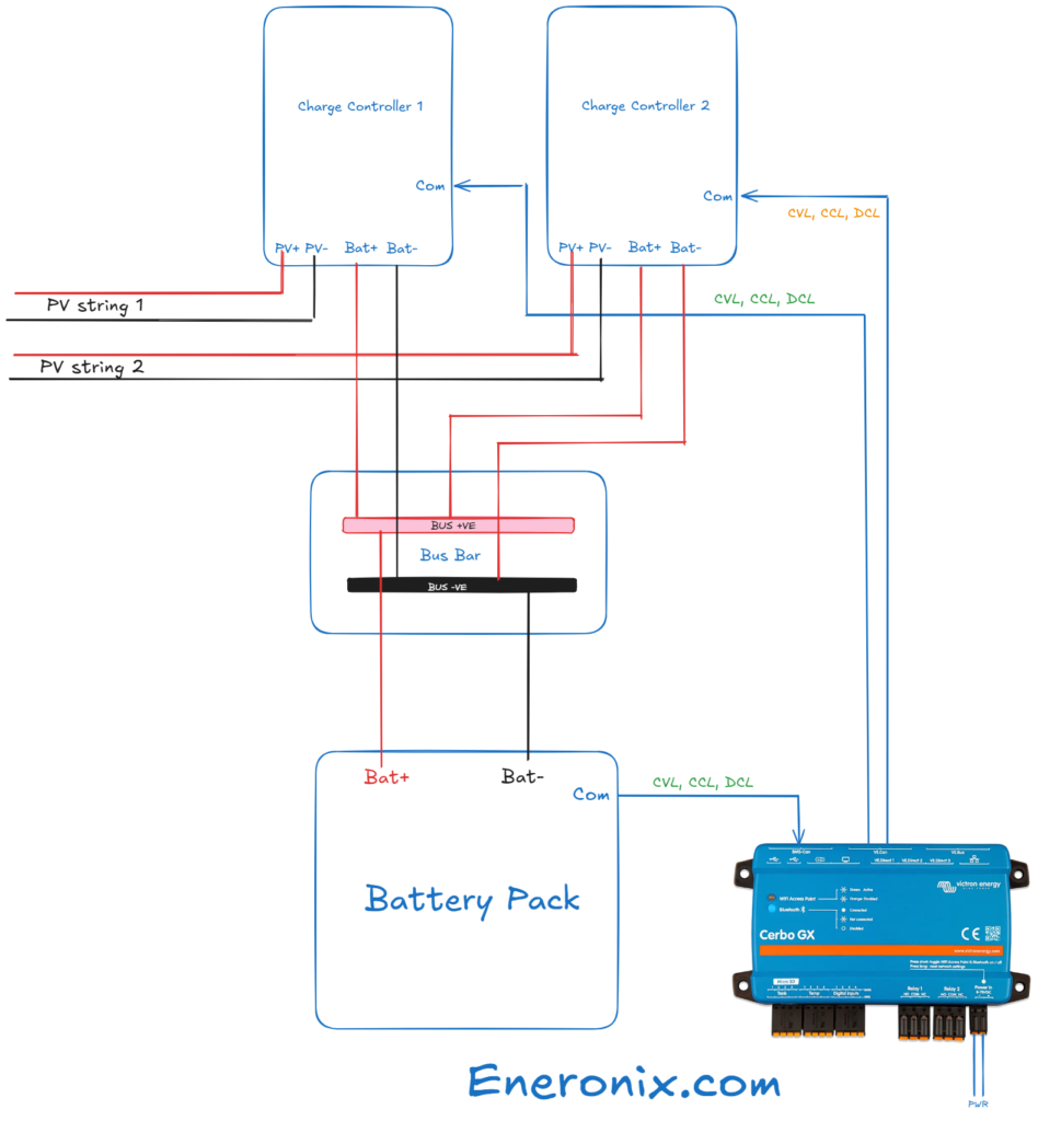
Scenario 3: Adding a Second MPPT Controller
When the combined array exceeds the existing controller’s output current capacity, a second MPPT controller is installed on a dedicated new array string or strings. The two controllers operate independently, each managing its own array input and delivering its output to the shared battery bank via separate cable runs. Both controllers connect to the Cerbo GX via VE.Can and both receive the CVL and CCL from the Pylontech BMS through the Cerbo GX. Neither controller requires synchronisation with the other. The second controller requires its own MPPT-to-battery cable run sized for its output current, its own fuse at the battery positive busbar, and its own VE.Can connection to the Cerbo GX.
Array Expansion Constraint Summary:
Adding panel to existing string -> 4S Voc 167.3V > 135V limit -> FAIL on 150V controller

Adding new parallel string -> output current 53.8A < 57A derated -> PASS within 150/60

Second MPPT controller -> independent operation, both receive CVL/CCL via Cerbo GX

New string fuse -> 15A solar string fuse per new string at combiner input

Combiner box capacity -> verify spare input terminal before adding string
For the MPPT controller voltage and current sizing methodology that governs the constraint checks in this section, refer to our engineering guides on how MPPT charge controllers work and how to select the right one and how to size and select an MPPT controller for a specific system.
Battery Bank Expansion
Battery bank expansion on the cluster system is achieved by adding Pylontech US3000C units in parallel with the existing four-unit bank. The expansion interacts with three constraints simultaneously: the maximum parallel string count on a single BMS, the charge and discharge current limits transmitted to the charge sources, and the DC busbar and fuse ratings on the battery positive bus.
The fundamental requirement for parallel string addition is that the new units must match the existing units in chemistry, nominal voltage, and capacity. Connecting a new Pylontech US3000C in parallel with four used units that have completed 500 cycles does not damage the new unit, but it produces two effects that must be understood. The first is an initial equalisation current that flows from the new fully charged unit into the used units as their state of charge equalises. The second is a permanent current imbalance during normal operation: the new unit with lower internal resistance carries a higher share of the discharge current, which accelerates its cycle accumulation relative to the used units.
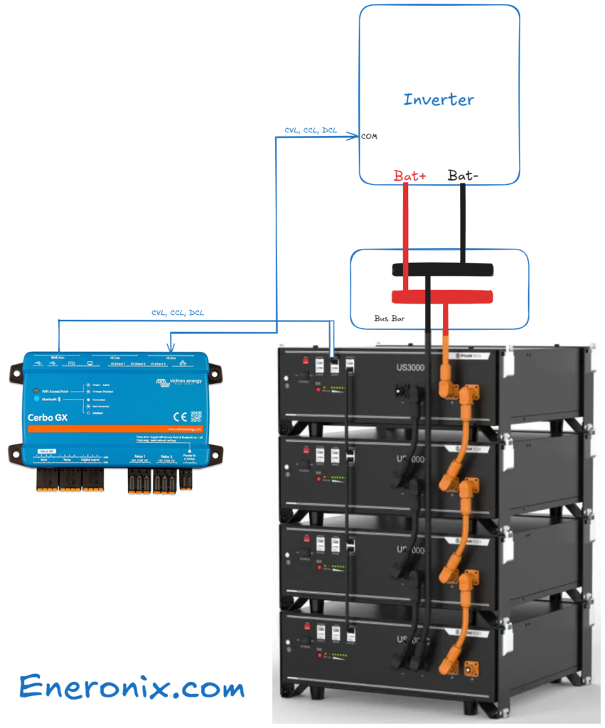
The four-string maximum on a single Pylontech BMS established in Post #12 means that expanding beyond four units requires a second BMS. The Pylontech architecture supports multiple BMS units communicating with the Cerbo GX, with each BMS managing its own string group. The Cerbo GX aggregates the CVL, CCL, and DCL from all BMS units and distributes the most conservative values to the charge sources. as shown here.
Constraint Check: Adding a Fifth Unit
Units required = 5 total

Maximum strings on single BMS = 4

5 > 4 -> second BMS required

Architecture: BMS-1 manages units 1-4, BMS-2 manages unit 5

Both BMS units connect to Cerbo GX via VE.Can-to-CAN adapter
Constraint Check: Adding One Unit to a Three-Unit Bank
Units = 4 total (3 existing + 1 new)

4 <= 4 maximum -> single BMS sufficient -> PASS

New CCL = 4 x 25A = 100A

New DCL = 4 x 37A = 148A

New usable capacity = 4 x 3,550Wh x 0.90 = 12,780Wh

New daily DoD = 4,916Wh / 12,780Wh = 38.5%
Each new Pylontech unit added to the bank requires an individual fuse at the battery positive busbar. A 50A MIDI fuse per unit satisfies the requirement that the fuse rating is greater than the unit’s maximum continuous discharge current of 37A and at or below the busbar cable’s derated current rating.
DoD and Autonomy After Expansion: Four Units to Six Units
New usable capacity = 6 x 3,550Wh x 0.90 = 19,170Wh

New daily DoD = 4,916Wh / 19,170Wh = 25.6%

New autonomy days = 19,170Wh / 4,916Wh = 3.9 days
For the battery bank sizing methodology and the parallel string limit that governs the constraint checks in this section, refer to our engineering guide on battery bank sizing, configuration, and BMS selection for off-grid systems.
Inverter Upgrade
An inverter upgrade is required when a load expansion increases the peak simultaneous AC load beyond the existing inverter’s continuous or surge rating. On the cluster system the existing Multiplus-II 48/3000 has a continuous rating of 3,000VA and a surge rating of 5,500VA. The peak simultaneous load at the time of original specification was 1,950W, leaving 1,050VA of continuous headroom and 3,550VA of surge headroom. Any load expansion that consumes this headroom beyond the rated limits requires either a replacement inverter or a second inverter in parallel configuration.
Upgrade Path 1: Replace with Higher-Rated Model
The Victron Multiplus-II range at 48V includes the 48/5000 at 5,000VA continuous and 9,000VA surge, and the 48/8000 at 8,000VA continuous and 16,000VA surge. The replacement process requires decommissioning the existing unit, installing the replacement, and reconfiguring the charge parameters in VEConfigure to match the battery bank’s CVL, CCL, and LVC settings. The DC cable and fuse requirements for the upgraded inverter must be recalculated for the new unit’s maximum DC input current:

Multiplus-II 48/5000 maximum DC input current:
I_DC = P_AC / (V_DC x η) = 5,000W / (48V x 0.92) = 113.2A

Existing cable: 35mm² derated at tropical ambient ≈ 120A

113.2A vs 120A derated -> marginal, less than 6% margin -> upgrade to 50mm²

50mm² derated at tropical ambient ≈ 145A

113.2A < 145A -> PASS with 28% margin

New fuse: 125A ANL at battery positive terminal
Upgrade Path 2: Parallel Second Multiplus-II 48/3000
Adding a second Multiplus-II 48/3000 in parallel with the existing unit doubles the combined continuous and surge ratings. The parallel configuration requires that both units are identical models running the same firmware version, and VEConfigure must be used to configure the parallel system before the second unit is energised alongside the first. The effective continuous rating of the parallel pair is not simply 6,000VA. Each unit must be operated at or below 70 to 75 percent of its individual continuous rating to maintain safe thermal margins:
Effective continuous rating of parallel pair:
P_effective = 2 x 3,000VA x 0.70 = 4,200VA
Combined DC current at full load:
I_DC_combined = 2 x 67.9A = 135.8A

Existing 35mm² cable: derated ≈ 120A

135.8A > 120A -> FAIL — DC cable upgrade required

Required cable: 50mm² derated at ≈ 145A

135.8A < 145A -> PASS

New busbar current: 135.8A -> existing 25x3mm copper at 200A -> PASS

New fuse: 150A ANL at battery positive terminal
Inverter Upgrade Path Comparison:
Replace with 48/5000 -> 5,000VA continuous, 9,000VA surge; DC cable upgrade to 50mm²

Parallel second 48/3000 -> 4,200VA effective continuous; DC cable to 50mm²; VEConfigure mandatory

Replace with 48/8000 -> 8,000VA continuous, 16,000VA surge; DC cable upgrade to 70mm²
For the inverter sizing methodology and surge verification that governs the constraint checks in this section, refer to our engineering guides on how to select and size an off-grid inverter and how to size and select an off-grid inverter — complete worked example.
Load Expansion
Load expansion is the expansion type that most frequently produces the field failure described in the introduction, because the new component — the load — is often connected by someone other than the original installer without any constraint analysis being performed. The binding constraint on load expansion is the peak simultaneous load, not the average load and not the individual new load in isolation. The correct load expansion calculation applies the same peak simultaneous load analysis from Post #8 to the expanded load profile:
Peak simultaneous load after expansion:
P_peak_new = P_peak_existing + P_new_load_running
Surge check:
P_surge_new = P_peak_existing + (P_new_motor x inrush_factor)
Both must satisfy:
P_peak_new  <= inverter continuous rating x 0.75 utilisation

P_surge_new <= inverter surge rating
Applying this to the second air conditioner addition on the cluster system. The existing peak simultaneous load is 1,950W. The new 1,500W air conditioner draws 1,667VA at a power factor of 0.90:
P_peak_new = 1,950W + 1,667VA = 3,617W

Inverter continuous rating = 3,000VA

3,617W > 3,000VA -> FAIL — inverter upgrade required before load addition

Surge check with new compressor starting while existing load runs:

P_surge_new = 1,950W + (1,667VA x 5) = 1,950 + 8,335 = 10,285W

Inverter surge rating = 5,500VA

10,285W >> 5,500VA -> FAIL at significant margin
The load expansion cannot proceed without an inverter upgrade. The upgrade to a Multiplus-II 48/5000 resolves both constraint failures:
After upgrade to Multiplus-II 48/5000:
P_peak_new = 3,617W vs 5,000VA continuous -> PASS at 72% utilisation

P_surge_new = 10,285W vs 9,000VA surge -> marginal FAIL

With soft starter on new air conditioner (inrush reduced to 3x):

P_surge_new = 1,950W + (1,667VA x 3) = 1,950 + 5,001 = 6,951W

6,951W vs 9,000VA surge -> PASS with 23% margin
The soft starter on the new air conditioner is not optional in this configuration. Without it the surge demand at compressor startup exceeds even the upgraded inverter’s surge rating. Load expansion also affects the battery bank’s daily energy demand and the solar array’s daily harvest requirement. The correct sequence for a load expansion planning exercise is: confirm the inverter constraint, then recalculate the daily energy demand with the new load, then check the battery bank autonomy, then check the array output against the new daily demand.
Load Expansion Checklist:
Peak simultaneous load check -> P_peak_new <= inverter continuous at 75% utilisation
Surge check -> P_surge_new <= inverter surge rating; soft starter if marginal

Daily energy demand update -> recalculate E_daily with new load included

Battery autonomy check -> new autonomy days = usable capacity / new E_daily

Array output check -> existing array output vs new E_daily on worst-case day

AC circuit check -> new load circuit cable and RCBO sized for new load current
For the peak simultaneous load methodology and surge analysis that governs the constraint checks in this section, refer to our engineering guides on how to select and size an off-grid inverter and how to size and select an off-grid inverter — complete worked example.
Cable and Fuse Upgrade for Expanded Circuits
Cable and fuse upgrades are the expansion element most consistently underestimated in expansion planning, because the existing cables are concealed once the installation is complete and their ratings are not visible without reference to the commissioning documentation or physical inspection. Every expansion that increases the current in an existing cable run must verify that the existing cable can carry the new current within its derated thermal limit before the expansion is energised.
Array expansion by new parallel string increases the current in the combiner-to-MPPT run. The new combined array current of three strings at 31.5A must be checked against the existing 6mm² cable’s derated rating. At tropical ambient in a compact installation, 6mm² cable derated carries approximately 46A, which comfortably accommodates 31.5A. No cable upgrade is required for the combiner-to-MPPT run on this specific expansion. The new string requires a new 4mm² solar-rated cable from the panel junction box to the combiner box and a 15A string fuse at the combiner input.
Battery bank expansion beyond four units requires a second BMS and a second set of battery-to-busbar cables. Each new Pylontech unit requires a dedicated cable from its positive terminal to the positive busbar, sized for the unit’s 37A maximum discharge current:
A_min = (0.0175 x 2m x 37A) / 0.48V = 1.30 / 0.48 = 2.70mm²

Thermal constraint: 10mm² satisfies 37A with tropical derating margin

Cable selected: 10mm² per unit, 50A MIDI fuse per unit at positive busbar
Inverter upgrade to the Multiplus-II 48/5000 requires the battery-to-inverter cable to be upgraded from 35mm² to 50mm² as established in Section 4. The existing 35mm² cable must be physically removed and replaced with 50mm² cable for the full length of the run. Partial replacement of a section of the run is not acceptable, because the thermal constraint applies to the entire run and the replaced section in series with the original section does not reduce the thermal stress on the original section.
Cable and Fuse Upgrade Reference by Expansion Type:
New array string -> 4mm² solar cable, 15A string fuse, check combiner output cable

Second MPPT controller -> new MPPT-to-battery run sized for controller output current

Battery units beyond 4 -> 10mm² per unit to busbar, 50A MIDI fuse per unit

Inverter upgrade to 48/5000 -> replace battery-to-inverter cable with 50mm², 125A ANL fuse

Parallel second Multiplus-II -> new 35mm² cable per unit to busbar, 150A ANL combined fuse

New AC load circuit -> 2.5mm² three-core, RCBO rated to load current per Post #11
For the two-constraint cable sizing methodology and fuse selection rules that govern the cable upgrades in this section, refer to our engineering guide on DC wiring, cable sizing, and fusing for off-grid systems.
Worked Example, Complete Expansion Specification
The cluster system as fully specified at Post #12 is the starting point for this expansion. The client requests two changes: adding a second 1,500W air conditioner to the load profile and increasing the battery bank to support three autonomy days at the new daily demand. The expansion constraint analysis is applied in sequence before any component is selected.
Step 1: Calculate New Daily Energy Demand
Second AC estimated usage: 1,500W x 4 effective hours = 6,000Wh

E_daily_new = 4,916Wh + 6,000Wh = 10,916Wh
Step 2: Check Inverter Constraint
New peak simultaneous load = 1,950W + 1,667VA = 3,617W

Multiplus-II 48/3000 continuous = 3,000VA

3,617W > 3,000VA -> FAIL — inverter upgrade required

Selected upgrade: Multiplus-II 48/5000

Continuous: 5,000VA, Surge: 9,000VA

3,617W vs 5,000VA -> PASS at 72% utilisation

Surge with soft starter (3x inrush):

1,950W + (1,667VA x 3) = 6,951W vs 9,000VA -> PASS

DC cable upgrade: 35mm² -> 50mm²

New fuse: 125A ANL at battery positive terminal
Step 3: Check Battery Bank for New Demand and Three-Day Autonomy
C_bank_required = (E_daily_new x N_autonomy) / DoD_usable

C_bank_required = (10,916Wh x 3) / 0.90 = 36,387Wh

Existing bank: 4 x 3,550Wh = 14,200Wh

Additional capacity required: 36,387 - 14,200 = 22,187Wh

Additional units: 22,187 / 3,550 = 6.25 -> 7 additional units

Total units: 4 existing + 7 new = 11 units

Maximum strings on single BMS = 4

11 units requires 3 BMS units (4 + 4 + 3)

Architecture: BMS-1: units 1-4, BMS-2: units 5-8, BMS-3: units 9-11

All three BMS units connect to Cerbo GX via VE.Can-to-CAN adapters

Total bank: 11 x 3,550Wh = 39,050Wh nameplate

Usable capacity: 39,050Wh x 0.90 = 35,145Wh

Daily DoD: 10,916Wh / 35,145Wh = 31.1%

Autonomy days: 35,145Wh / 10,916Wh = 3.22 days -> PASS
Step 4: Check Array Output Against New Daily Demand
Existing array derated output: 2,400W x 0.718 = 1,724W

Daily harvest (5.5 peak sun hours): 1,724W x 5.5h = 9,482Wh

New daily demand: 10,916Wh

9,482Wh < 10,916Wh -> array undersized by 1,434Wh per day

Additional array: minimum 1 additional panel equivalent

Single panel string not viable (Vmp 34V too low for MPPT tracking)

New 3S string: 3 x 400W = 1,200W additional

New total array: 2,400W + 1,200W = 3,600W

New daily harvest: 3,600W x 0.718 x 5.5h = 14,206Wh

14,206Wh > 10,916Wh -> PASS with 30% margin

New third string Voc: 3 x 41V x 1.0203 = 125.5V < 135V limit -> PASS

New combined MPPT output: (3,600W x 0.718) / 48V = 53.9A < 57A -> PASS
Step 5: Complete Expansion Component List
Expansion Specification:
Inverter replacement -> Victron Multiplus-II 48/5000 (replaces 48/3000)

Battery addition -> 7 x Pylontech US3000C (total 11 units)

BMS addition -> 2 x Pylontech BMS module (manages new unit groups)

CAN adapters -> 2 x VE.Can-to-CAN adapter (one per new BMS)

Array addition -> 3 x 400W panels, new 3S string

Array wiring -> 4mm² solar cable, 15A string fuse, combiner box expansion

DC cable upgrade -> replace battery-to-inverter 35mm² with 50mm², full run

Fuse upgrade -> replace 100A ANL with 125A ANL at battery positive terminal

New busbar positions -> 7 x 50A MIDI fuse holders for new battery units

AC circuit addition -> 2.5mm² three-core, 10A RCBO for second air conditioner

Soft starter -> install on second air conditioner compressor
Generator Review for Expanded System
The generator that was adequate for the original cluster system must be reviewed whenever the battery bank capacity or the AC load profile changes significantly. Both have changed in the expansion specified in Section 7. The battery bank has grown from 14.2kWh to 39.05kWh and the peak AC load has grown from 1,950W to 3,617W. Both changes affect the generator’s ability to recharge the bank and serve the loads simultaneously.
The generator charge power available is the generator’s rated output minus the simultaneous AC load that must be served while the generator is running:
Original system generator charge power:
P_charge = P_generator - P_load = 5,000W - 1,950W = 3,050W

Charge current at 48V: I_charge = 3,050W / 48V = 63.5A -> adequate

Expanded system with original 5kVA generator:

P_charge = 5,000W - 3,617W = 1,383W

Charge current at 48V: I_charge = 1,383W / 48V = 28.8A -> inadequate

Recharge time at 1,383W for 80% DoD recharge:

E_recharge = 35,145Wh x 0.80 = 28,116Wh

T_recharge = 28,116Wh / 1,383W = 20.3 hours -> unacceptable
The original 5kVA generator is inadequate for the expanded system. The generator must be sized to serve the full expanded AC load plus a minimum charging power of 3,000W:
Minimum generator output required:
P_generator = P_load + P_charge_minimum + margin

P_generator = 3,617W + 3,000W + (0.20 x 6,617W) = 7,940W

Selected generator: 8kVA

Recharge time at 3,000W charge power on 8kVA generator:

T_recharge = 28,116Wh / 3,000W = 9.4 hours -> acceptable

New AC input current limit on Multiplus-II 48/5000:

I_AC_limit = (8,000W - 3,617W) / 230V = 19.1A

Set AC input current limit to 19A in VEConfigure
The generator cable and protection device must also be resized for the new generator’s rated output current. An 8kVA generator at 230V produces a rated output current of 34.8A. The generator input cable must be sized for 34.8A continuous with the two-constraint methodology from Post #10, and the MCB at the generator output terminals must be rated to protect the cable rather than the generator’s internal winding protection.
Generator Review Checklist for System Expansions:
Generator charge power check  -> P_generator - P_peak_load >= 2,000W minimum charging headroom

Recharge time calculation -> E_bank x 0.80 / P_charge <= 10 hours for acceptable recharge

Generator upgrade trigger -> existing generator charge power < 2,000W after load expansion

New generator sizing -> P_load + P_charge_min + 20% margin

AC input current limit update -> recalculate and reprogram in VEConfigure after generator change

Generator cable resizing -> rated output current, two-constraint framework from Post #10
Conclusion
The second air conditioner that shut down the system in the introduction was not a rogue appliance. It was a correctly functioning load connected to a system that had not been analysed for its addition. The constraint analysis in this post would have identified the inverter capacity failure and the surge failure before the unit was purchased, determined that an inverter upgrade was required, and flagged the cascade of subsequent changes — DC cable upgrade, battery bank expansion for the new autonomy requirement, array expansion for the new daily demand, and generator upgrade for the expanded bank — that a single load addition triggered.
This cascade is the characteristic pattern of off-grid system expansion. Because every component in the system was sized to the original load profile with defined margins, adding a load that consumes those margins forces the margins to be rebuilt by upgrading the constraining components. The constraint analysis makes this cascade visible at the planning stage, where it can be sequenced, budgeted, and communicated to the client before any work begins. The same expansion discovered sequentially during installation costs significantly more in labour, return visits, and client confidence than a single documented expansion specification produced before the first component is ordered.
The expansion specification produced in Section 7 is the same type of document as the original system specification produced across Posts #1 through #12: a set of verified component selections, each checked against defined constraints, with cable sizes, fuse ratings, and communication architecture updated to reflect the expanded system. It can be handed to any competent installer and executed without further engineering judgment at the installation stage.
In the next post we examine system economics: the payback period calculation, the total cost of ownership over the system’s service life, and the framework for comparing an off-grid investment against the alternatives available to the same client.
For the component sizing methodologies that govern the expansion constraint checks in this post, refer to our engineering guides on how to size and select an MPPT controller for a specific system, how to select and size an off-grid inverter, battery bank sizing, configuration, and BMS selection, and DC wiring, cable sizing, and fusing for off-grid systems.

I am Engr. Ubokobong Ekpenyong, a solar specialist and lithium battery systems engineer with over five years of hands-on experience designing, assembling, and commissioning off-grid solar and energy storage systems. My work focuses on lithium battery pack architecture, BMS configuration, and system reliability in off-grid and high-demand environments.
This guide really breaks down the technical aspects of expanding an off-grid system in a clear and practical way. I especially appreciated the detailed steps for checking battery bank capacity and inverter constraints—those are often where things go wrong. It’s reassuring to see a framework that helps avoid common pitfalls like overloading or under-sizing components during expansion.
That’s a great question to be thinking through for small setups. The short answer is that adding panels to an existing string is almost always the first instinct, but it’s also the scenario most likely to hit a constraint, specifically the cold Voc limit on the MPPT controller. As the guide shows, adding just one panel to a 3S string on a 150V controller pushes the cold Voc past the 90% safety threshold entirely. Adding a parallel string keeps the string voltage the same and only increases output current, which is usually the safer path as long as the controller’s output current headroom isn’t already tight. For very small setups, a second MPPT controller is often the cleanest solution when both options are constrained. Worth running the numbers before committing either way.
The detailed walkthrough of adding panels versus adding parallel strings is really insightful. I’ve been debating which approach works best for small off-grid setups, and this guide makes the considerations much clearer. It’s also helpful how it highlights checking inverter and battery constraints before expanding.
Thank you for the kind words! You’re absolutely right, battery bank capacity and inverter constraints are where most expansion failures originate in the field. The opening scenario in this guide (the second AC that shut down the Multiplus-II) is a real-world example of exactly that: no single component failed, but the inverter’s continuous and surge headroom had never been checked before the new load was added. The goal with this framework is to make those checks non-negotiable before any expansion component is purchased, not after. Glad it came across to you practically.