Introduction
A lithium battery that “won’t charge past 85–90%” is one of the most common complaints installers and system owners report. The system shows adequate solar input, the charger reaches its configured absorption voltage, and yet usable capacity appears to shrink over time. In many cases, the battery is declared degraded, undersized, or defective within its first year of service.
In reality, the sun is not the problem and neither is the battery chemistry.
The root cause is almost always a misunderstanding of what the absorption stage actually does in a lithium system. Most charge controllers still label this stage using lead-acid terminology, and many installers assume absorption “finishes the charge” in the same way it does for flooded or AGM batteries. As a result, absorption time is often configured arbitrarily two hours because “that’s standard” without reference to lithium behavior, BMS design, or cell-balancing requirements.
This leads to a predictable failure mode: cells slowly drift out of balance, one cell reaches its over-voltage limit early, the BMS protects the pack, and the user loses access to a growing portion of the battery’s capacity. What appears to be early-life capacity loss is, in most cases, not degradation at all it is imbalance limiting usable energy.
Understanding this distinction matters financially and operationally. Misdiagnosed “capacity loss” results in unnecessary warranty claims, premature battery replacements, repeated service visits, and systems that never deliver their rated performance. All of it is preventable with correct absorption configuration based on how lithium batteries actually behave during constant-voltage charging.
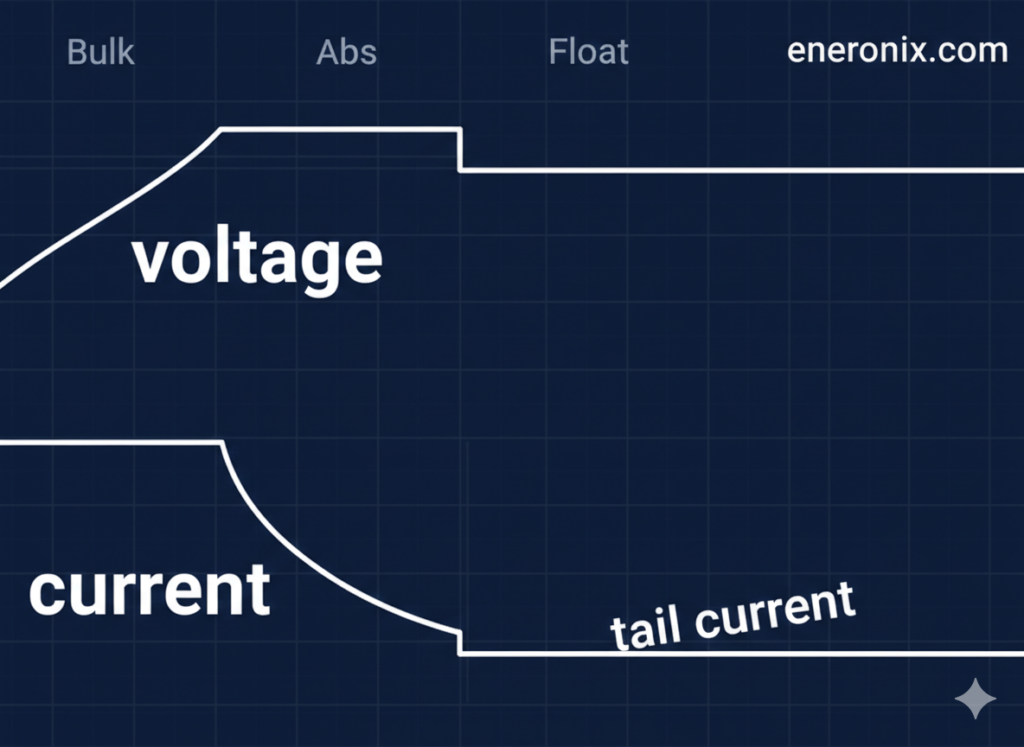
This is the third article in our series on lithium battery charging. In the previous post, we covered the bulk (constant-current) phase that delivers 80–90% of pack capacity. By the time pack voltage reaches the absorption setting (14.2–14.4 V for 12 V systems), the battery typically sits at 90–95% state of charge, and the controller transitions into the absorption (constant-voltage) phase. This is where conventional wisdom about “finishing the charge” diverges sharply from lithium chemistry reality
Read: What’s Really Happening During Bulk Charging in Lithium Battery
This article explains what really happens during the absorption phase in lithium batteries, why charging is effectively complete within minutes, why absorption time exists primarily to support cell balancing, and how to calculate absorption duration based on measurable conditions rather than inherited lead-acid conventions.
TL;DR: If a lithium battery won’t charge past 85–90%, the problem is almost never the battery it's insufficient absorption time for cell balancing, not incomplete charging or early degradation.
What’s Actually Happening During Constant Voltage Phase
The CV Taper Process
Most installers expect absorption to work like lead-acid systems, where the battery holds voltage at the gassing threshold for 2–4 hours while waiting for slow oxygen-hydrogen recombination kinetics. The chemistry itself limits the absorption rate cut it short, and gases evolve instead of being stored as charge.

Lithium batteries work nothing like this. There is no gas recombination. The absorption (constant-voltage) phase reaches 95% state of charge within 5–10 minutes of hitting the voltage limit. Current tapers from 40–50A down to 15–20A in the first 10 minutes as ion concentration approaches equilibrium. From a chemistry perspective, charging is essentially complete within 30 minutes.
So why do lithium charge controllers run absorption for 1–2 hours or longer? Not for charging. For cell balancing. Those remaining 60–90 minutes are passive balancing circuits operating at 30–100mA, draining high-voltage cells while lower cells catch up. This is maintenance electronics, not battery chemistry.
During the constant-voltage phase, the controller holds pack voltage constant at the target (14.2–14.4V typical for 12V systems). Current decreases exponentially as the battery approaches equilibrium. This isn’t a slow chemical process like gas recombination it’s the thermodynamic approach to ion concentration equilibrium.
Here’s what a typical taper curve looks like for a 100Ah pack at 14.4V:
- Entry: 50A (end of CC phase)
- 10 minutes: 95% SOC, current at 20A
- 20 minutes: 97% SOC, current at 10A
- 40 minutes: 98.5% SOC, current at 3A
- 60+ minutes: 99%+ SOC, current <1A
Most of the capacity is delivered in the first 10–15 minutes. The remaining time is spent chasing the final 1–2% with diminishing returns. Current decay is exponential, not linear each successive halving of current takes progressively longer.
Why Charging Is “Complete” So Quickly
At 14.4V (3.60V per cell), the anode is approaching lithium saturation. The thermodynamic driving force for further ion insertion decreases, so current tapers because equilibrium is being approached not because of a kinetic limitation waiting to catch up.
Compare this to lead-acid, where 2–4 hour absorption waits for O₂/H₂ recombination. Slow chemical kinetics limit the process. In lithium systems, there’s no gas to recombine, just an ion concentration gradient flattening out. Reaching 95% state of charge within 5–10 minutes is the chemistry-appropriate timeframe.
lithium CC/CV charging behavior
If absorption were really about “finishing the charge,” it would end at 30 minutes when chemistry reaches 98–99% state of charge. It doesn’t end there because the balancing circuits need time. Charging is complete balancing is not.
Most “capacity loss” complaints in the first 1–2 years trace back to inadequate balancing time. Cells drift 50–100mV apart over months. One cell hits the BMS overvoltage limit before the pack is fully charged. The customer sees “battery only charges to 85%” when the actual problem is imbalanced cells preventing full pack access.
The rest of this article covers what cell balancing actually is, the mathematics of passive balancing rates, why solar variability interrupts balancing, and how to calculate absorption time based on actual balancing requirements rather than guesswork.
What Is Cell Balancing and Why Does It Matter?
Why Cells Become Imbalanced
Manufacturing tolerance: cells from factory have 2-5% capacity variance. Temperature gradients: cells in different pack locations experience different temps during cycling, creating capacity and voltage differences. Self-discharge variance: though small (<3% annually), accumulates differently per cell over months. Age-related drift: cells degrade at slightly different rates over hundreds of cycles.
Result: voltage spread develops over weeks/months of cycling. New pack, cells within 10mV at rest. After 50 cycles without adequate balancing: 50-80mV spread. After 200 cycles: 100-150mV spread.
Why this matters: one high cell hits BMS limit (3.65V) before others fully charged, prevents accessing full pack capacity. Pack might show 85% SOC when one cell at limit, others at 3.58-3.60V with room remaining.
How Passive Balancing Works
Most BMS use passive balancing: bleed resistors drain current from high-voltage cells. Activation threshold: typically 3.45-3.50V/cell. Current capacity: 30-100mA per cell (BMS dependent).
Operation: When cell exceeds threshold, BMS closes MOSFET, current flows through resistor, dissipates as heat. While high cell being drained at 30-100mA, lower cells continue receiving charge from pack current. Over time, voltages converge.
passive cell balancing specifications
Why passive not active: Active balancing (charge transfer between cells) requires complex DC-DC converters, increases BMS cost 3-5×. Passive sufficient for most applications despite energy waste as heat.
Energy loss trivial: 50mA × 3.6V × 2 hours = 0.36Wh per cell. Negligible compared to 100-300Ah cell capacity (360-1080Wh).
Why Balancing Only Happens During Absorption
Balancing circuits activate only above threshold voltage (3.45-3.50V/cell). During discharge or storage at lower SOC: balancing disabled. During bulk/CC phase: voltage rising through threshold range but current too high for effective balancing. Balancing drain (30-100mA) insignificant compared to 50A+ charge current.
During absorption/CV phase: voltage held constant above threshold, current tapered low enough that balancing drain represents meaningful fraction of total current. At 5A pack current, 50mA balancing is 1% of current. At 0.5A pack current, 50mA is 10%. Balancing becomes effective.
This is why absorption voltage must be 3.55-3.60V (14.2-14.4V for 12V). Lower voltages (14.0V/3.50V) might not reliably exceed balancing activation threshold. Absorption phase holds cells at voltage where balancing operates continuously.
The Mathematics of Passive Balancing Time
How Long Does Balancing Actually Take?
Most installers drastically underestimate required balancing time.
Calculation example:
Scenario: 280Ah cell at 3.58V, three siblings at 3.54V. Voltage spread 40mV.
Capacity difference: ~1.5-2Ah (voltage-SOC curve steep at top, small voltage difference = small capacity difference)
Balancing current: 50mA (typical BMS passive balancing rate)
Time to equalize: 1.5Ah ÷ 0.05A = 30 hours
Not 30 minutes. 30 hours of continuous balancing at full activation voltage.
Balancing only active during absorption phase. 2-hour daily absorption = 2 hours balancing time accumulated. Need 15 days to correct 40mV drift. If cells drift 5mV per week from cycling, 2-hour daily absorption barely maintains equilibrium.
Larger cells worse:
- 100Ah cells, 40mV spread: ~0.8Ah difference, 16 hours balancing time
- 280Ah cells, 40mV spread: ~2Ah difference, 40 hours balancing time
- 300Ah cells, 50mV spread: ~2.5Ah difference, 50 hours balancing time
Balancing time scales with cell capacity. Larger cells need proportionally more time. This is why “set absorption to 2 hours” fails on large-format cells. The physics don’t scale.
Initial Top-Balancing Requirements
New pack from factory: cells may have 50-100mV spread from manufacturing tolerance plus shipping/storage time creating initial imbalance.
Initial top-balance procedure: 12-48 hours continuous at absorption voltage. Not 2 hours. Not 6 hours. Minimum 12 hours, often 24-48 hours for large cells (280Ah+).
Current-limited charging (0.05-0.2C if possible) prevents overheating during extended session. At 0.2C on 280Ah cells, 56A generates I²R heat. Extended duration at high current thermally stresses cells.
Monitor cell voltages during session. Complete when all cells within 20-30mV at absorption voltage. Skipping this: cells never properly balance, drift worsens over months. “Battery loses capacity after 6 months” often traces to inadequate initial balancing, not cell degradation.
Ongoing Balancing Maintenance
Daily cycling creates ongoing drift from temperature gradients, capacity variance manifesting during charge/discharge cycles.
Required balancing time depends on:
- Depth of discharge: deeper cycling = more drift per cycle
- Temperature during cycling: gradients create imbalance
- Current rates: higher current = more temperature spread = more drift
- Existing cell variance: well-matched cells drift slower
Recommendations by cycling depth:
- Light cycling (20-30% DOD): 1-2 hours absorption sufficient
- Moderate cycling (40-60% DOD): 2-4 hours absorption needed
- Heavy cycling (70-90% DOD): 4-8 hours absorption several times per week, or 2 hours daily + 8-12 hour weekly extended session
Not universal settings. Based on measurable cell drift rate over time.
Why Solar Variability Makes Balancing Worse
The Cloud Interruption Problem
Grid-charged systems: stable current throughout CV phase, balancing circuits operate continuously at full effectiveness. Controller holds 14.4V constant, balancing active entire duration.
Solar systems: current varies with irradiance. Clouds interrupt balancing by dropping pack voltage below activation threshold.
Scenario: 2-hour absorption timer set, partly cloudy day.
Sunny period (0-20 minutes):
- Pack voltage 14.4V, current tapering normally
- Balancing active, circuits draining high cells at 50mA
Cloud passes (20-35 minutes):
- Available power drops 60%
- Pack voltage sags to 13.8V (3.45V/cell)
- Below balancing threshold (3.50V typical)
- Balancing circuits deactivate
- 15 minutes: no balancing occurring
Cloud clears (35-65 minutes):
- Voltage recovers to 14.4V
- Balancing resumes
- 30 minutes active balancing
Another cloud (65-90 minutes):
- Voltage sags again, balancing stops
- Clears at 90 minutes
Final period (90-120 minutes):
- 30 minutes active balancing
Total effective balancing: 20 + 30 + 30 = 80 minutes out of 2-hour timer.
Controller logged “2 hours absorption complete.” Cells received <half expected balancing time. Over weeks, cells drift 5-10mV weekly despite “adequate” absorption settings.
Tail Current Exit Problems
Tail current termination: controller exits absorption when current drops below threshold (e.g., 2A for 100Ah pack). Sounds chemistry-appropriate, exit when battery acceptance near-zero.
Problem: concurrent loads break the logic.
Base loads: inverter idle (50-150W), refrigerator (100-200W), pumps, BMS quiescent draw. Total: 3-5A continuous.
Charger output: 8A total (5A to battery, 3A to loads). Controller measures charger output, sees 8A, never reaches 2A tail current threshold. Absorption runs until timer backup (if exists) or indefinitely.
Or worse: Cloud passes, PV power drops, charger output falls to 1A. Tail current threshold met prematurely. Absorption exits after 20 minutes when balancing needs 90+ minutes.
Fix requires battery shunt measuring actual battery current, not charger output. Most solar installations lack this. Shunt adds $100-200 plus installation complexity.
Time-based absorption more reliable than tail current for solar applications without battery shunt. Predictable minimum balancing time regardless of load or weather variability.
How to Calculate Required Absorption Time
Assessment-Based Calculation
Check current cell voltage spread at rest (not under charge/discharge). Wait 2+ hours after charging stops for voltage to settle.
Spread <30mV: Well-balanced. 1-2 hours absorption adequate for maintenance.
Spread 30-50mV: Moderate imbalance. 2-3 hours absorption needed to prevent further drift.
Spread 50-80mV: Significant imbalance. 4-6 hours absorption needed, or immediate extended session.
Spread >80mV: Severe imbalance. Extended balancing session (8-24 hours) required before returning to normal schedule. Daily absorption insufficient to correct this level of drift.
Reassess monthly: measure cell spread, track trend. Spread increasing 10-20mV per month indicates absorption time insufficient for cycling pattern. Spread stable or decreasing indicates adequate balancing.
Example: Pack showing 65mV spread after 3 months at 2-hour absorption. Increase to 4 hours, reassess in 30 days. If spread decreasing toward 40-50mV, setting adequate. If still increasing, need extended session plus longer daily absorption.
Cycling-Depth-Based Recommendation
Light cycling (<30% DOD daily): 1-2 hours absorption. Shallow cycling creates minimal temperature gradients, less opportunity for drift.
Moderate cycling (30-60% DOD): 2-4 hours absorption. Standard off-grid daily cycling pattern.
Heavy cycling (60-90% DOD): 4-6 hours absorption, or 2 hours daily + 6-12 hour weekly extended session. Deep cycling traverses full voltage curve, manufacturing tolerance accumulates as voltage drift.
Why DOD matters: Deeper cycling creates larger temperature differentials between cells (higher current = more I²R heating), more opportunity for capacity variance to manifest as voltage differences.
Solar variability adjustment: Add 30-50% to calculated time for systems with frequent cloud interruption. Accounts for interrupted balancing periods.
- 2-hour calculated need → 3 hours actual setting
- 4-hour calculated need → 6 hours actual setting
Monitor cell spread monthly to validate. If spread still increasing, insufficient time despite calculations. Increase further or schedule extended sessions.
Practical Absorption Configuration and Diagnostics
Time-Based vs. Tail Current Termination
Time-based termination: Exits after fixed duration regardless of current.
- Advantage: Predictable balancing time allocation
- Disadvantage: Clouds mean less effective balancing within window, but timer still expires
- Best for: Systems without battery shunt, need guaranteed minimum balancing time
Tail current termination: Exits when current drops below threshold (e.g., 0.01-0.02C).
- Advantage: Chemistry-appropriate, exits when battery actually tapered
- Disadvantage: Concurrent loads prevent reaching threshold, or premature exit during clouds
- Requires battery shunt measuring actual battery current, not charger output
- Best for: Grid-tied or systems with dedicated battery current measurement
- Rare in solar: Most installations lack shunt ($100-200 hardware + installation)
Hybrid approach: Exit after X hours OR Y amps, whichever first.
- Advantage: Prevents indefinite absorption (tail current never met) and excessive time (if chemistry complete early)
- Disadvantage: Not all controllers support combined criteria
- Example: 3 hours OR 1A tail current, whichever first
- Best for: Controllers offering this logic
Recommendation for solar: Time-based, duration calculated from Section 6 methods. Add 30-50% margin for cloud interruption.
Recommended Settings by Application
Off-grid daily cycling (most common):
- Absorption: 2-3 hours
- Tail current (if shunt available): 0.01-0.02C
- Monitor: Monthly cell voltage check, adjust if spread >50mV
RV/Mobile variable usage:
- Absorption: 2-3 hours
- Accept incomplete absorption some days (limited charging window while driving)
- Extended monthly balancing: 6-12 hours when parked with shore power
Grid-tied backup (rarely cycles):
- Absorption: 1-2 hours (minimal daily balancing needed, cells don’t drift much)
- Extended quarterly session: 4-6 hours to maintain balance
Heavy daily cycling (>70% DOD):
- Absorption: 4-6 hours, or split approach: 2 hours daily + 8-12 hours weekly
- Monitor weekly: Heavy cycling causes faster drift, requires active management
Initial installation (new pack):
- First charge: 12-24 hours continuous absorption
- Current limit: 0.05-0.2C (prevents thermal stress during extended session)
- Complete: When all cells within 20-30mV
- Then: Transition to application-appropriate schedule
Diagnostic Indicators and Corrective Actions
Symptom 1: Increasing cell voltage spread over weeks
- Measure: Cells monthly at rest (2+ hours after charging)
- Spread increasing 10-20mV/month: Absorption time insufficient
- Action: Increase daily absorption 1-2 hours, or add weekly extended session
Symptom 2: "Battery won't charge past 85-90%"
- Check cells during charging: One at 3.65V, others at 3.58-3.60V
- BMS protecting high cell before pack full
- Not capacity loss: Imbalance limiting pack access
- Action: 12-24 hour extended balancing session immediately
Symptom 3: BMS overvoltage trips during charging
- Daily trips during absorption phase
- Check cells: High cell at/near 3.65V, others significantly lower (50-100mV spread)
- Severe imbalance preventing charge completion
- Action: Extended balancing (12-24 hours) + increase ongoing absorption by 2-3 hours
Symptom 4: Capacity appears to decrease (cells healthy)
- Usable capacity drops from 95% to 80% over 6-12 months
- Individual cell test shows healthy capacity
- Problem: Imbalance preventing full capacity access, not degradation
- Action: Top-balance procedure (24-48 hours), adjust absorption schedule based on drift rate
Critical insight: Most "capacity loss" complaints in first 1-2 years are cell imbalance, not degradation. Adequate balancing time prevents misdiagnosis and unnecessary warranty claims/cell replacement.
Conclusion
In lithium battery systems, the absorption stage does not exist to finish charging the battery. Charging is already essentially complete within minutes of entering the constant voltage phase, typically reaching 95 percent state of charge very quickly. The remaining absorption time serves a different purpose entirely. It exists to allow slow BMS cell balancing to occur, not to complete battery chemistry.
Passive balancing operates at very low currents, usually between 30 and 100 milliamps, which means correcting normal cell voltage drift requires accumulated time measured in tens of hours. A two-hour daily absorption setting may be marginally sufficient for lightly cycled systems, but it is inadequate for heavily cycled systems or for large format lithium cells such as 280-amp hour and above. In solar installations, absorption effectiveness is further reduced by irradiance variability, which frequently interrupts balancing and cuts effective balancing time to a fraction of the configured duration.
Because of this, absorption time cannot be treated as a fixed or universal setting. It must be determined based on measurable conditions, including cell voltage spread at rest, daily depth of discharge, individual cell capacity, and the reliability of the charging source. Systems experiencing increasing voltage spread despite apparently adequate absorption time are not suffering from battery degradation. They are suffering from insufficient balancing time.
Initial top balancing is critical to long term performance. New battery packs commonly begin operation with significant cell imbalance due to manufacturing tolerance and storage history. Without a continuous absorption session of 12 to 48 hours during commissioning, this imbalance persists and worsens over time. Many cases of apparent capacity loss within the first year are not caused by aging or damage, but by imbalance that prevents access to the battery’s full usable energy.
When absorption is correctly understood as a balancing stage rather than a charging stage, configuration shifts away from inherited lead acid assumptions and toward lithium specific maintenance. Properly configured absorption prevents most early life capacity complaints, reduces unnecessary warranty claims, and ensures lithium battery systems deliver their expected performance throughout their service life.
The next article in this series examines the float stage, why it is often unnecessary or harmful in lithium systems, and how to configure it safely when it cannot be disabled.

Hi, i am Engr. Ubokobong a solar specialist and lithium battery systems engineer, with over five years of practical experience designing, assembling, and analyzing lithium battery packs for solar and energy storage applications, and installation. His interests center on cell architecture, BMS behavior, system reliability, of lithium batteries in off-grid and high-demand environments.