Introduction
What "Bulk" Actually Means for Lithium
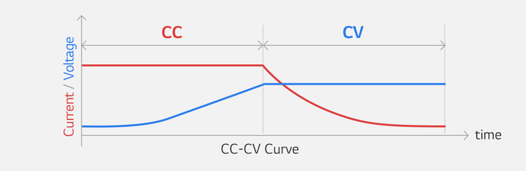
We established in our previous post that lithium battery uses two-stage CC/CV charging, not three-stage bulk/absorption/float. The “bulk” label is legacy terminology from lead-acid systems. For lead-acid, bulk means pushing high current through sulfation resistance until reaching gassing threshold. For lithium, bulk is just constant-current charging with no resistance barrier.
Also Read Part 1: Lead-Acid vs Lithium Charging: Key Differences
The real complexity isn’t chemistry. It’s BMS behavior operating on cell-level conditions that most charge controllers can’t see.
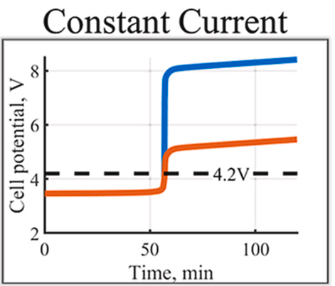
Your charge controller displays “Bulk,” measures pack voltage climbing from 13.2V to 14.4V, delivers rated current, then transitions to absorption. Looks straightforward. Meanwhile, the BMS monitors 4-16 individual cells, samples each voltage 100-1000 times per second, compares against overvoltage thresholds (typically 3.65V/cell), and progressively throttles current as any cell approaches limits. Temperature sensors trigger protection: charging cutoff below 0-5°C (lithium plating risk), current reduction above 45-50°C (accelerated SEI degradation). Pack voltage is aggregate behavior. Cell-level conditions determine actual limits.
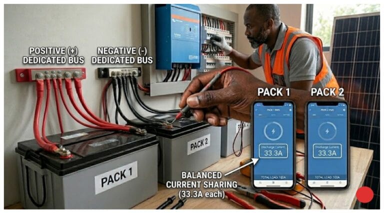
Most “battery won’t accept current” problems trace to BMS protection, not equipment failure. Available current 60A, battery accepting 8A, installer checks MPPT settings, array voltage, wiring resistance. Actual cause: BMS pre-throttling to protect one cell at 3.62V while others sit at 3.54V. Cell imbalance, not hardware fault.

This post covers CC phase mechanics, BMS pre-throttling logic, temperature constraints, and diagnostic procedures based on cell-level behavior. Understanding what’s happening inside the BMS during “bulk” changes how you troubleshoot charging problems.
What’s Actually Happening Inside Cells During Constant Current
The Ion Movement Process
During CC charging, lithium ions (Li⁺) move from cathode (LiFePO₄) to anode (graphite). Intercalation process: ions insert into spaces between graphite layers at the anode. Electrons flow through external circuit to maintain charge neutrality. Each ion carries one unit of charge.
Rate-limiting factors:
- Ionic conductivity in liquid electrolyte
- Solid-state diffusion into particle interiors
- Interface kinetics at electrode/electrolyte boundary
These limitations remain relatively constant across SOC range. Cell at 20% SOC accepts current at approximately same rate as cell at 80% SOC. No sulfation-type resistance barrier builds up during discharge. Graphite anode and olivine-structured LiFePO₄ cathode maintain structural integrity throughout cycling. Intercalation sites remain accessible.
Internal resistance (DC impedance) varies ~10-15% from 20% to 80% SOC in LiFePO₄ cells. Compare to lead-acid: 50-200% resistance increase when deeply discharged due to sulfation. This relatively constant acceptance rate is why lithium charges in 1.5-2 hours what takes lead-acid 4-6 hours.
Practical observation: 100Ah LiFePO₄ cell accepts 50A (0.5C) at 15% SOC, continues accepting 50A at 40% SOC, 60% SOC, 85% SOC. Current stays constant until pack voltage reaches programmed limit. Limitation isn’t chemistry resistance, it’s ionic transport rates that don’t change significantly with SOC.
Why Voltage Rises During CC Phase
Voltage rise during CC charging is thermodynamic, not resistive. As lithium accumulates in anode and depletes from cathode, electrochemical potential difference between electrodes increases. This is Nernst equation behavior: voltage depends on ion concentration ratio.
LiFePO₄ voltage-SOC relationship:
- 3.20V at 20% SOC
- 3.25V at 40% SOC
- 3.30V at 60% SOC
- 3.40V at 80% SOC
- Steep climb: 3.45V at 85%, 3.55V at 92%, 3.60V at 95%
The “flat” discharge curve everyone mentions applies to 20-80% SOC range. Voltage still rises ~200mV across that window. Final 10-15% SOC shows rapid voltage increase as anode approaches lithium saturation.
This is predictable equilibrium behavior. Apply 50A to discharged cell, voltage follows characteristic curve based on how many ions have moved. No chemistry “catching up” like lead-acid gas recombination. No resistance breaking down like sulfation dissolution.
Why Does CC Phase End When It Does?
No Chemistry-Defined Transition Point
Lead-acid bulk ends at gassing threshold (14.4-14.8V for 12V systems). Chemistry dictates this transition. Above that voltage, water electrolysis begins, defining the shift from bulk to absorption.
Lithium bulk ends at whatever voltage you programmed. Typical: 14.2-14.4V for 12V LiFePO₄ systems (3.55-3.60V/cell). This is installer choice based on practical constraints, not chemical necessity. No gassing threshold exists. No electrolyte decomposition occurs at normal charge voltages.
Three factors determine bulk voltage setting:
- BMS overvoltage protection limit – Typically 3.65V/cell (14.6V for 12V pack). Hard cutoff point where BMS opens charge path.
- Headroom margin – 50-100mV below BMS limit. Accounts for cell imbalance, voltage measurement tolerance, dynamic voltage during current flow.
- Balancing activation threshold – Most BMS passive balancing activates at 3.45-3.50V/cell. Bulk voltage must exceed this for balancing circuits to operate during CV phase.
Set voltage too low (14.0V/3.50V per cell): May not reliably activate balancing. Cells drift over time. Also leaves capacity on table, extends CV phase duration.
Set voltage too high (14.6V/3.65V per cell): Charging right to BMS limit. Any cell variance triggers protection. Abrupt charge termination before pack reaches target SOC.
Why 14.2-14.4V Specifically?
BMS overvoltage protection typically trips at 14.6V (3.65V/cell) for 12V systems. 48V systems: 58.4V (3.65V × 16 cells). This is hard limit programmed into BMS firmware.
Setting bulk voltage to 14.6V: charging to the limit with zero margin. Cell imbalance of 30mV means one cell hits 3.65V while others at 3.62V. BMS trips, charging stops, pack sits at 85-90% SOC. Customer sees “battery won’t charge fully.”
Setting bulk to 14.2-14.4V provides 50-100mV headroom per cell:
- At 14.4V pack voltage: cells range 3.58-3.62V (assuming 40mV imbalance)
- Highest cell still 30-70mV below trip point
- BMS allows charging to continue
- Balancing circuits active (above 3.45-3.50V threshold)
Trade-offs:
- 14.2V (3.55V/cell): Maximum headroom (100mV), very reliable, stops at ~90% SOC
- 14.3V (3.575V/cell): Good balance, 75mV headroom, ~92% SOC
- 14.4V (3.60V/cell): Minimum safe headroom (50mV), ~95% SOC, requires well-balanced cells
Personal practice: 14.3V for most installations. 14.4V only for packs with confirmed cell balance <30mV spread at rest.
What happens at 14.6V: Installed system with bulk set to BMS limit. Daily BMS overvoltage trips during charging. Customer complaint: “battery charges to 80% then stops.” Checked individual cells: 80-120mV spread. One weak cell hitting 3.65V while others at 3.56-3.60V. Not capacity loss, cell imbalance preventing full pack access. Reduced bulk to 14.3V, scheduled extended balancing session. Problem resolved. BMS was protecting cells correctly, configuration gave it no margin to work with.
Why Lithium Charges Faster Than Lead-Acid
No Sulfation Barrier
Lead-acid bulk charging involves breaking down PbSO₄ crystals formed during discharge. Chemical conversion process: PbSO₄ → Pb (negative plate) and PbO₂ (positive plate). Slow reaction kinetics limit charge acceptance, especially when deeply discharged. Effective charge acceptance: 0.1-0.2C early in bulk phase even when applying higher current. Remaining energy dissipates as heat or drives side reactions.
Lithium intercalation has no conversion barrier. Li⁺ ions insert into existing crystallographic sites in graphite anode. Physical movement into lattice spaces, not chemical transformation. No resistive layer forms during discharge that must be overcome during charge.
Charge acceptance comparison:
- Lead-acid (deeply discharged): 0.1-0.2C effective acceptance
- Lead-acid (partially discharged): 0.2-0.3C effective acceptance
- LiFePO₄ (any discharge depth): 0.5-1C continuous acceptance
100Ah lead-acid battery: might accept 10-20A when deeply discharged, gradually increasing to 30A as sulfation breaks down. Same capacity LiFePO₄: accepts 50A (0.5C) or 100A (1C) from 10% SOC through 85% SOC without degradation.
Charging Time Comparison
System example: 100Ah nominal capacity, 50A available charge current, charging from 10% to 90% SOC (80Ah delivered).
LiFePO₄:
- Constant 50A acceptance throughout SOC range
- 80Ah ÷ 50A = 1.6 hours
- Actual time slightly longer due to efficiency losses (~5%)
- Real-world: 1.7-1.8 hours to 90% SOC
Lead-acid (AGM):
- Variable acceptance: 15A average first hour, 25A second hour, 35A third hour
- Sulfation resistance decreases as charging progresses
- Need ~4-5 hours to deliver same 80Ah
- Then requires 2-4 hours absorption for gas recombination
- Total: 6-9 hours to equivalent charge state
Solar installation observation: Same 5kW array, same MPPT controller, swapped battery chemistry. Lead-acid system: bulk phase continuing until 2-3pm on sunny days. LiFePO₄ system: bulk complete by 10-11am, transitions to absorption. MPPT didn’t get more powerful. Battery chemistry accepts current without resistance barriers.
Customer expectation management required. “Why is battery already full? It’s only noon.” Not a problem, it’s chemistry. Need to explain faster charging is normal lithium behavior, not equipment malfunction or undersized battery bank.
What Is the BMS Actually Doing During Bulk?
Continuous Cell-Level Monitoring
BMS samples individual cell voltages at 100-1000 Hz depending on design. Not pack voltage, individual cells. 12V system: 4 cells in series (4S). 48V system: 16 cells (16S). Each cell monitored independently.
Typical BMS architecture:
- Cell voltage measurement: ±10mV accuracy
- Temperature sensors: 1-4 per pack, ±2°C accuracy
- Current measurement: Hall effect or shunt, ±1% accuracy
- Sampling rate: 100-1000 samples/second per cell
- Decision loop: 10-100ms update rate for protection actions
Most installers treat BMS as binary switch: charging allowed or not allowed. Reality is, progressive current management is based on cell-level conditions. BMS communicates with charge controller (when protocols support it) or directly controls charge path MOSFETs.
Pack voltage your charge controller sees is sum of individual cell voltages. 48V pack reading 54.0V might have cells at: 3.375V, 3.380V, 3.375V, 3.370V… (16 cells). Or might have: 3.340V (×15 cells) + 3.460V (1 cell). Both show same pack voltage. BMS response completely different.
BMS Pre-Throttling
BMS doesn’t wait for cell to hit hard limit (3.65V) then suddenly cut charging. Progressive current reduction as highest cell approaches overvoltage threshold.
Typical pre-throttling algorithm (varies by BMS manufacturer):
Highest cell voltage → Allowed charge current
- <3.55V: 100% rated current (1C if rated for it)
- 3.55-3.58V: 100% rated current
- 3.58-3.60V: 80% rated current
- 3.60-3.62V: 50% rated current
- 3.62-3.63V: 30% rated current
- 3.63-3.64V: 10% rated current
- ≥3.65V: 0% (cutoff)
Some BMS units communicate via CAN bus to charge controller, sending current limit commands. Others directly control charge FET, opening it progressively (PWM control) to limit current. Result same: charge current reduces before hard voltage limit reached.
Scenario installer sees:
- MPPT display: “Available PV power: 3000W, Battery voltage: 53.2V”
- Expected charge current: 3000W ÷ 53.2V ≈ 56A
- Actual charge current: 8A
- Installer conclusion: MPPT fault, wiring issue, array problem
Actual cause (check individual cells):
- 15 cells: 3.325V each = 49.875V
- 1 cell: 3.425V
- Pack voltage: 53.3V
- Highest cell 3.425V triggered pre-throttling at 80% reduction
- Not equipment failure, protective throttling from cell imbalance
BMS protecting that high cell from reaching 3.65V while others still have capacity remaining. Current limited to slow the rate at which highest cell climbs.
Diagnostic Procedure – BMS Protection vs. Equipment Failure
When charge current is lower than expected, check in this order:
Step 1: Individual cell voltages
- Access BMS display/app showing per-cell voltage
- Look for outliers: any cell >50mV higher than pack average?
- If yes: BMS pre-throttling. Problem is cell imbalance, not equipment.
- Solution: Extended balancing session (covered in Post 3), not hardware replacement.
Step 2: Cell temperatures
- Check BMS temperature readings
- Below 5°C? Charging disabled or severely limited (lithium plating protection)
- Above 45-50°C? Charging throttled or disabled (thermal runaway prevention)
- If temperature outside range: thermal management issue, not equipment fault
Step 3: Pack voltage vs. bulk setting
- Is pack voltage within 0.2V of bulk voltage limit?
- If yes: transitioning to CV phase, current taper is normal
- This isn’t a problem, it’s end of CC phase
Step 4: Only then check system/charger
- MPPT tracking voltage
- Array wiring voltage drop
- Shading or soiling on panels
- Charge controller derating due to internal temperature
In my experience, 80% of “battery won’t accept current” service calls are Step 1 (BMS pre-throttling from imbalance) or Step 2 (temperature protection). 15% are Step 3 (normal CV taper misinterpreted). 5% are actual Step 4 system issues.
Checking Steps 1-2 takes 2 minutes with BMS monitoring. Skipping directly to Step 4 wastes hours troubleshooting MPPT settings and measuring array voltages when BMS was protecting cells correctly the entire time.
Temperature Effects on the CC Phase
Cold Temperature Limitations
Below ~5°C, lithium plating occurs on anode surface during charging. Metallic lithium deposits on graphite surface instead of intercalating into lattice. Permanent damage: capacity loss from lithium consumption, dendrite formation creating internal short risk.
Mechanism:
Ion diffusion rate through electrolyte and into graphite particles decreases exponentially with temperature. At low temps, ions arrive at anode surface faster than they can intercalate. Surface concentration builds up. Thermodynamically favorable for metallic lithium deposition rather than insertion into graphite.
Arrhenius relationship:
Diffusion coefficient drops ~50% per 10°C temperature decrease. At 0°C, diffusion rate is 1/8th the rate at 25°C. Apply 50A charge current at 0°C, ions can’t intercalate fast enough, plate on surface instead.
BMS thermal protection response:
- Below 0°C: Charging completely disabled (hard cutoff)
- 0-5°C: Charging disabled or severely limited (BMS dependent)
- 5-10°C: Progressive current reduction (1C → 0.5C → 0.2C as temp decreases)
- Above 10°C: Full rated current allowed
Temperature thresholds vary by BMS manufacturer. Some conservative designs says no charging below 5°C. While aggressive designs, allows 0.1C charging down to 0°C. Cell manufacturers typically specify 0°C minimum charge temperature in datasheets.
Installer observation:
Off-grid system, winter morning. Full sun at 7am, array producing 4kW, MPPT ready, battery at 40% SOC. Charge current: 0A. BMS display shows cell temperature 2°C, charging disabled. Not equipment fault. Cells need to warm above 5°C threshold.
Warming occurs through:
- Ambient temperature rise (sun warms battery enclosure)
- Self-heating from discharge loads (internal resistance × current² generates heat)
- Active heating if installed (heating pads, temperature-controlled enclosure)
Same system in summer: charging begins at 6:30am when cells reach 12°C. Winter: charging delayed until 9-10am when ambient warms cells above 5°C. 2-3 hour daily charging delay during cold months. Not malfunction, thermal protection preventing plating damage.
Hot Temperature Limitations
Above 45-50°C, accelerated side reactions degrade SEI layer on anode. Electrolyte decomposition increases exponentially with temperature. Charging at elevated temperature accelerates calendar aging: capacity loss from SEI thickening, increased impedance, lithium inventory consumption.
Not immediate damage. Thermal runaway doesn’t occur until 60-80°C (cell chemistry dependent). But charging at 50°C ages cells 2-3× faster than charging at 25°C. After 1000 cycles at 50°C, capacity might be 75% of original vs. 85% for same cycles at 25°C.
BMS thermal protection:
- 45-50°C: Current reduction (1C → 0.5C → 0.2C)
- Above 50-55°C: Charging disabled
- Thresholds BMS-dependent, typically 50°C cutoff
Thermal protection creates on-off cycling behavior when cells operate near threshold. Cells hit 51°C, BMS opens charge FET, current drops to zero, cells cool to 49°C over 2-3 minutes, BMS closes FET, charging resumes, cells heat back to 51°C. Cycle repeats.
What The Installer sees:
Charge current oscillating 0A → 40A → 0A → 40A every few minutes. Current won’t taper smoothly during CV phase. Absorption never completes because current keeps resetting to high values.
Root cause:
Thermal management failure. Battery enclosure inadequately ventilated, cells can’t reject heat during charging. Summer afternoon, ambient 35°C, poor airflow, cells reach 48-52°C during bulk phase. BMS cycling is correct protective behavior.
Fix:
Improve ventilation (forced air if necessary), reduce charge current to lower heat generation (I²R losses), add thermal mass or active cooling. Not a BMS problem, not a charge controller problem. Thermal design problem.
Temperature-Related Troubleshooting
Cold charging issues:
- Symptom: No charging despite available PV, battery SOC low
- Check: BMS cell temperature reading
- Below 5°C? Charging disabled by design, not fault
- Solution: Wait for ambient warming, add heat source, or accept delayed charging in winter
- Verify temperature sensor accuracy: IR thermometer on cell cans, compare to BMS reading
Hot charging issues:
- Symptom: Charging starts/stops repeatedly, won’t complete
- Check: Cell temperature during charging
- Above 45°C? Thermal cycling from protection threshold
- Solution: Improve ventilation, reduce charge current, add cooling
- Measure actual cell temperature, not enclosure air temp
Sensor failure detection:
- BMS shows -20°C when ambient is 15°C: sensor failure (open circuit)
- BMS shows 60°C when cells cool to touch: sensor failure (short circuit)
- Verify with independent temperature measurement before replacing BMS
- Failed sensor typically triggers BMS fault, disables charging entirely
In both temperature extremes, BMS protecting cells from damage. Cold prevents lithium plating. Hot prevents accelerated aging. Not equipment malfunction, operating as designed. Troubleshooting focuses on why cells reached temperature extremes, not why BMS responded to them.
Common Bulk Phase Problems and What They Actually Mean
Problem 1: "Battery Won't Accept Full Charge Current"
Symptom: Available charge power 3kW (60A at 50V), battery accepting 8-15A.
Diagnostic sequence:
- Check individual cell voltages first
- One cell ≥50mV higher than others → BMS pre-throttling
- Example: 15 cells at 3.52V, one cell at 3.61V
- BMS protecting high cell from reaching 3.65V limit
- Not equipment fault, cell imbalance issue
- Check cell temperatures
- Below 5°C → charging disabled/limited (plating protection)
- Above 45°C → charging throttled (aging protection)
- Either condition: thermal issue, not charge system fault
- Check pack voltage vs. bulk setting
- Pack at 54.2V, bulk set to 54.4V → normal CV transition behavior
- Current tapering as approaching voltage limit
- Not a problem, expected end-of-CC phase
- Only then check system:
- MPPT tracking voltage and sweep function
- DC wiring voltage drop under load
- Array shading, soiling, or physical damage
- Charge controller thermal derating
Case example: Customer complaint, system accepting only 12A with 65A available. Checked cells: one at 3.59V, others at 3.51-3.53V. BMS pre-throttling confirmed. Ran 8-hour top-balance session at 0.1C. Cell spread reduced to 25mV. Next charge cycle: full 65A acceptance until pack reached 54.3V. No hardware replaced. Problem was imbalance, not equipment.
Problem 2: "Charging Stops at 80% SOC"
Symptom: Battery charges to 75-85% displayed SOC, then stops. Won’t reach 100%.
Actual cause: One cell hitting overvoltage protection while others have remaining capacity.
Diagnostic:
- Check individual cells when charging stops
- Typical finding: One cell at 3.64-3.65V, others at 3.57-3.60V
- BMS correctly protecting weakest cell
- Pack voltage might read 54.4-54.6V (one high cell + others lower)
Not capacity loss. Pack still has full capacity. Cell imbalance prevents accessing it. Weak cell acts as bottleneck, hits voltage limit first, triggers protection before pack fully charged.
Solution: Extended balancing session to equalize cells. Not BMS replacement, not cell replacement (unless one cell genuinely damaged). Top-balance procedure: charge to absorption voltage, hold 12-24 hours at 0.05-0.1C current limit. Passive balancing drains high cells, equalizes pack.
Why SOC displays mislead: SOC calculated from pack voltage or coulomb counting with voltage-based calibration. When cells imbalanced, pack voltage reaches “full” point while some cells not actually full. Display shows 85% because algorithm assumes balanced pack. Actual: One cell 100%, others 90%, average ~92%.
Problem 3: "Voltage Rises Too Fast During Bulk"
Symptom: Pack voltage climbs from 52V to 54V in 20 minutes, should take 90+ minutes.
Possible causes:
- SOC estimation error: Battery not as discharged as display indicates. Voltage rises fast because starting from higher SOC than displayed. Coulomb counter drift or reset causes SOC miscalculation.
- Weak cell pulling voltage up: One cell significantly lower capacity than others. Reaches high voltage prematurely while others still have room. Cell-level voltage check confirms.
- Undersized pack for load: Deep cycling to very low SOC daily. Voltage climbs quickly from lower starting point. Not a fault, system design issue (pack too small for loads).
Diagnostic: Check individual cell voltages during “fast” rise. All cells tracking together and rising uniformly → SOC error or undersized pack. One cell significantly higher → weak/damaged cell.
Problem 4: "Bulk Phase Takes Forever"
Symptom: Charge current consistently low (10-20A when 50A+ available), bulk phase extends 4-5 hours.
Causes ranked by frequency:
- BMS pre-throttling (see Problem 1): Cell imbalance limiting current
- Temperature protection: Cells outside optimal range
- Insufficient available power: Array undersized, shaded, or soiled
- MPPT misconfiguration: Bulk voltage set too low, transitions to CV prematurely
- Wiring losses: Excessive voltage drop at high current
Diagnostic approach: Start with BMS data (cells, temperature), then work outward to system components.
What Percentage of Capacity Is Delivered During Bulk?
CC phase delivers 80-90% of total capacity depending on where bulk voltage is set and initial SOC.
Typical scenario: Charging from 10% to full capacity (100%).
Bulk voltage 14.4V (3.60V/cell): CC phase ends at approximately 90-95% SOC. Delivered: 80-85% of total capacity during bulk. Remaining 10-15% delivered during CV/absorption phase.
Bulk voltage 14.2V (3.55V/cell): CC phase ends at approximately 85-90% SOC. Delivered: 75-80% of total capacity during bulk. Remaining 15-20% delivered during CV phase.
Capacity delivery rate:
100Ah battery, 50A charge current (0.5C):
- 10% to 90% SOC = 80Ah delivered
- 80Ah ÷ 50A = 1.6 hours theoretical
- Add 5-8% efficiency losses: 1.7-1.8 hours actual
200Ah battery, 100A charge current (0.5C):
- 10% to 90% SOC = 160Ah delivered
- 160Ah ÷ 100A = 1.6 hours theoretical
- 1.7-1.8 hours actual including losses
Charge rate scales linearly with capacity. Time to complete bulk phase remains constant for given C-rate.
Why this matters:
Time savings with lithium occur during bulk/CC phase. Lead-acid same 80Ah delivery requires 4-6 hours due to sulfation resistance and lower charge acceptance. Lithium completes in under 2 hours.
Final 10-15% capacity delivered during CV phase takes disproportionately longer. Current tapers exponentially as approaching equilibrium. From 90% to 95% SOC might take 15-20 minutes. From 95% to 98% another 20-30 minutes. Final 2% can take 30-60 minutes as current drops to milliamps.
Heavy lifting happens during bulk. By time pack voltage reaches absorption setting, charging is 80-90% complete from capacity perspective. What remains is finishing charge (10-15% capacity) plus cell balancing time (unrelated to capacity delivery, pure maintenance function).
Understanding this ratio is critical for absorption time configuration covered in Post 3. Installers who think “absorption finishes the charge” miss that charging was mostly finished within 10 minutes of entering absorption. The remaining 1-2 hours isn’t charging, it’s balancing.
Practical Takeaways for Bulk Phase Configuration
Key Configuration Points
Bulk voltage: 14.2-14.4V for 12V LiFePO₄ systems (3.55-3.60V/cell)
- 48V systems: 56.8-57.6V (16S configuration)
- 24V systems: 28.4-28.8V (8S configuration)
Voltage selection criteria:
Leave 50-100mV headroom below BMS overvoltage limit:
- BMS limit 3.65V/cell → bulk 3.55-3.60V/cell
- BMS limit 3.70V/cell → bulk 3.60-3.65V/cell (some high-voltage chemistries)
Ensure voltage exceeds balancing activation threshold:
- Most BMS: balancing activates 3.45-3.50V/cell
- Bulk voltage must be ≥3.55V to reliably activate balancing during CV phase
- Setting bulk to 3.50V risks inconsistent balancing activation
Don’t set bulk = BMS protection limit. Zero margin for cell variance. Guaranteed BMS trips with any imbalance.
Don’t set bulk significantly different from absorption. Lithium has no gassing threshold requiring voltage change between stages. Bulk = absorption voltage for proper CC/CV operation.
Temperature compensation:
0mV/°C (disabled). Non-negotiable. LiFePO₄ cells don’t require voltage adjustment for temperature like lead-acid does. Leaving compensation enabled causes overvoltage when cold, undervoltage when hot.
Diagnostic Approach When Problems Occur
Standard diagnostic sequence:
Step 1: Individual cell voltages
- Access BMS monitoring (display, app, CAN bus data)
- Check voltage spread at rest: >50mV indicates imbalance
- Check voltage spread during charging: identifies which cell limiting current
- If imbalanced: schedule balancing session, not hardware replacement
Step 2: Cell temperatures
- Check BMS temperature sensor readings
- <5°C: charging disabled by design (plating protection)
- 45°C: charging throttled by design (aging protection)
- If out of range: address thermal management, not charge system
Step 3: Pack voltage vs. bulk setting
- Is pack within 0.3V of bulk voltage?
- If yes: normal transition to CV phase, current taper expected
- Not a problem, end of CC phase
Step 4: System-level checks
- MPPT input voltage and tracking
- DC circuit voltage drop under load
- Array output (shading, soiling, damage)
- Charge controller temperature derating
Time allocation for troubleshooting:
- Steps 1-2: 2-5 minutes (BMS data review)
- Step 3: 30 seconds (voltage comparison)
- Step 4: 15-30 minutes (system measurements)
Check BMS data first. Saves hours troubleshooting system when BMS was protecting cells correctly.
Common misdiagnosis pattern:
Installer skips to Step 4, spends 2 hours checking MPPT settings, measuring array voltage, testing wiring continuity. Problem was Step 1 (cell imbalance) entire time. BMS pre-throttling visible in 30 seconds if checked first.
Conclusion
In lithium systems, the bulk phase is pure constant-current charging. There is no sulfation to overcome and no chemical conversion bottleneck. Voltage rises predictably as lithium-ion concentration gradients shift between electrodes, not because resistive layers are being broken down. Charge acceptance remains essentially constant from roughly 10% to 85% state of charge, which is why lithium reaches full charge in 1.5 to 2 hours, compared to 4 to 6 hours for lead-acid.
The complexity is not the chemistry. It is BMS behavior managing cell-level limits that charge controllers cannot see. While the controller monitors only pack voltage, the BMS continuously samples individual cell voltages often hundreds of times per second and progressively throttles current as any cell approaches its overvoltage threshold (typically ~3.65 V). Charging is disabled at low temperatures (below ~5 °C) to prevent lithium plating and reduced at elevated temperatures (above ~45 °C) to limit accelerated aging. Without visibility into these protections, normal BMS actions are often mistaken for charger or array faults.
Most “battery won’t accept current” complaints trace to one of three causes: cell imbalance triggering BMS pre-throttling (one cell 50 100 mV higher than the rest), temperature outside the safe charging window, or normal transition toward constant-voltage operation as pack voltage approaches the bulk limit. Effective troubleshooting starts at the cell level. Checking individual cell voltages, temperatures, and pack voltage takes minutes. Skipping directly to system-level diagnostics can consume hours and rarely identifies the root cause.
By the end of the bulk (CC) phase, a lithium battery is typically 80–90% charged. Most of the usable capacity has already been delivered at maximum current. What follows during absorption is where confusion increases. Many assume absorption “finishes the charge” in the same way it does for lead-acid. In reality, lithium reaches approximately 95% state of charge within minutes of entering the constant-voltage phase. The remaining time is not driven by charging chemistry.
In post 3 we will examine what actually happens during the absorption/CV phase, why current tapers in minutes rather than hours, how cell balancing works, and why it not slow charge acceptance dominates absorption time. Passive balancing currents of 30–100 mA require tens of hours of accumulated high-voltage time to correct typical 50–100 mV cell imbalances. This explains why fixed absorption timers can be either insufficient or excessive depending on pack condition, and why variable solar input often prevents effective balancing despite seemingly correct settings.
The term “absorption” implies slow chemical uptake of charge. For lithium, that process is largely complete within minutes. What remains is balancing electronics operating at milliamp levels while the chemistry sits near equilibrium. Understanding this distinction is the key to configuring absorption based on lithium-specific balancing requirements rather than inherited lead-acid conventions.

I am Engr. Ubokobong Ekpenyong, a solar specialist and lithium battery systems engineer with over five years of hands-on experience designing, assembling, and commissioning off-grid solar and energy storage systems. My work focuses on lithium battery pack architecture, BMS configuration, and system reliability in off-grid and high-demand environments.