Introduction
Most people buying a lithium battery only see the label on the case 100Ah, 48V, LiFePO₄ and assume the performance will match the print. But the real story of a battery’s quality, safety, and lifespan is written inside the pack, in places the average buyer will never get to see. Behind that clean metal enclosure is a complex system of cells, electronics, welds, sensors, and protection circuits that determine whether the battery will last ten years, or fail before the next dry season.
In today’s solar market especially across Africa and Nigeria where demand is booming the difference between a reliable lithium battery and a problematic one often comes down to internal engineering. While some packs follow strict manufacturing standards with matched cells, robust bus bars, and intelligent Battery Management Systems. Others cut corners with reused EV cells, fragile nickel strips, or BMS boards that collapse under inverter surge loads. The real challenge is that from the outside, both look identical.
This article takes you inside the architecture of modern lithium battery packs, breaking down the components, design decisions, and failure points that matter most.
From the outside, a battery is a monolithic block of energy. But to truly understand what you’re buying and what separates a decade-long workhorse from a premature failure you must start by understanding its most fundamental building block: the lithium cell.
Lithium Cell as the Fundamental Unit
A lithium cell is the smallest functional unit within a battery pack. It is a sealed electrochemical system that stores and releases energy through controlled ion movement. Each cell contains a positive electrode (cathode), a negative electrode (anode), a separator that prevents internal short circuits, and an electrolyte that enables lithium ions to move between electrodes during charge and discharge.
When you see battery specifications such as LiFePO₄ (Lithium Iron Phosphate) or NMC (Nickel Manganese Cobalt) are listed on a battery label, they refer specifically to the cathode chemistry inside these individual cells. This chemistry determines the cell’s fundamental behavior: nominal voltage, energy density, thermal stability, allowable current, degradation rate, and overall safety profile. For an engineer, chemistry selection is the first and most consequential decision in battery pack design, because no external circuitry can override the intrinsic limits of the cell itself.
Role of the Cell Within a Battery Pack
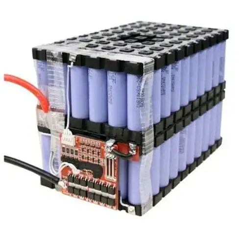
No single lithium cell powers a home or business on its own. Instead, a battery pack is formed by electrically and mechanically organizing many cells into a coordinated system. Within this system, cells serve two primary functions:
 Providing Voltage
Cells are connected in series to increase voltage. A single LiFePO₄ cell produces approximately 3.2V. By connecting sixteen cells in series, a nominal 51.2 V (48 V class) battery pack is formed.
Providing Capacity
Cells are connected in parallel to increase capacity and current capability. For example, four 25 Ah cells connected in parallel behave electrically as a single 100 Ah unit.
Because series-connected cells must all carry the same current, the performance of the entire pack is constrained by the weakest cell in the chain. If one cell degrades faster, drifts in voltage, or develops higher internal resistance, it limits usable capacity and accelerates overall pack failure. This is why cell matching and ongoing balance are critical at the pack level.
Clarifying the Hierarchy: Cell, Module, and Pack
Understanding internal battery architecture requires clear distinction between three structural levels:
- Cell
The basic electrochemical unit, such as a single 3.2 V, 25 Ah LiFePO₄ cell. All energy storage and degradation originate here.
- Module
A structured grouping of cells electrically connected often in a mix of series and parallel and mechanically supported within a frame. Modules simplify manufacturing, testing, and service, and may include local sensing or balancing components, like the NTC for temperature sensing in module level.
- Pack
The complete, user-facing system that integrates one or more modules with a master Battery Management System, protection devices, sensors, wiring, and enclosure. The pack interfaces with external loads and chargers, but it does not change the intrinsic behavior of the cells it contains.
Why This Distinction Matters
Two batteries may share identical labels 48 V, 100 Ah, LiFePO₄ yet perform very differently over time. The divergence often begins at the cell and module level.
In a well-engineered pack, matched cells are grouped into stable modules with low-resistance current paths and monitored continuously by a solid BMS. In poorly engineered packs, cells may be loosely assembled, inconsistently matched or reused cells, or connected with undersized interconnects (nickel strip, busbar) creating imbalance, excess heat, and premature failure. So externally, both batteries look the same; internally, one is structurally sound, while the other is inherently unstable.
At its core, every lithium battery pack is only as good as the cells it is built from and the way those cells are organized. The lithium cell is the foundation, and all higher-level design choices either reinforce that foundation or expose its weaknesses.
Cell Chemistries and Their Internal Differences
While all lithium cells share the same fundamental internal structure, the choice of cathode and anode materials fundamentally changes how a cell behaves. Voltage range, energy density, thermal stability, degradation rate, and current capability are all direct consequences of chemistry. External electronics cannot override these intrinsic properties.
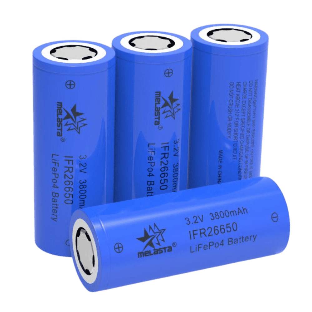
Lithium Iron Phosphate (LiFePO₄ – LFP)
LiFePO₄ cells use a lithium iron phosphate cathode paired with a graphite anode. Internally, the iron-phosphate crystal structure is highly stable, forming strong bonds that resist oxygen release even under abuse conditions.
This internal stability results in:
- A nominal cell voltage of approximately 3.2 V
- Lower energy density compared to nickel-based chemistries
- Exceptional thermal tolerance and cycle life
- Reduced risk of thermal runaway

The trade-off is size and weight: achieving high capacity requires more active material and physical volume. For stationary energy storage and solar applications where longevity and safety outweigh compactness LFP remains the dominant choice.
Lithium Nickel Manganese Cobalt (NMC)
NMC cells employ a layered cathode composed of nickel, manganese, and cobalt in varying ratios. Nickel increases energy density, manganese improves structural stability, and cobalt enhances conductivity and cycle performance.
Internally, this layered oxide structure allows:
- Higher nominal voltages around 3.6–3.7 V
- Significantly higher energy density than LFP
- Strong performance in applications requiring compact size

However, the same structure is less thermally stable than iron phosphate. NMC cells require tighter voltage control, precise thermal management, and conservative current limits. These cells are widely used in electric vehicles and high-energy portable systems, where size and weight are critical.
Lithium Cobalt Oxide (LCO)
LCO is one of the earliest commercial lithium chemistries. It uses a cobalt-rich cathode paired with a graphite anode, offering very high energy density at the cell level.
Internally, LCO cells exhibit:
- Nominal voltages around 3.7 V
- High capacity per unit volume
- Limited thermal stability and cycle life
Because cobalt-rich cathodes release oxygen at elevated temperatures, LCO cells are inherently less tolerant of abuse. Their use is largely restricted to consumer electronics such as smartphones and laptops, where strict power limits and controlled environments reduce risk.
Lithium Nickel Cobalt Aluminum (NCA)
NCA chemistry replaces manganese with aluminum in the cathode structure. Aluminum improves conductivity and reduces structural degradation under high load conditions.
Internally, NCA cells offer:
- High energy density comparable to or exceeding NMC
- Nominal voltages around 3.6–3.7 V
- Improved longevity under controlled thermal conditions
Despite these advantages, NCA cells remain sensitive to overcharge and high temperatures. They demand advanced thermal management and precise BMS control, which limits their use primarily to electric vehicles and aerospace-grade applications rather than stationary storage.
Lithium Titanate (LTO)
LTO cells replace the conventional graphite anode with lithium titanate, fundamentally altering internal electrochemical behavior. This change raises the anode potential, significantly reducing the risk of lithium plating.
Internally, LTO cells are characterized by:
- A much lower nominal cell voltage of approximately 2.3 V
- Extremely long cycle life, often exceeding 10,000 cycles
- Exceptional fast-charge capability
- Outstanding low-temperature performance
The cost of these advantages is very low energy density. LTO cells are physically large for their capacity and remain expensive, restricting their use to specialized industrial, military, and high-reliability applications.
Why Chemistry Choice Cannot Be “Fixed” Later
No Battery Management System, inverter, or charger can transform one chemistry into another. Safety margins, lifespan, and performance ceilings are embedded at the cell level through material selection and internal structure.
When two batteries share identical external ratings but use different chemistries, their real-world behavior under heat, surge loads, and long-term cycling will diverge significantly. Thus, mixing two batteries with different chemistry is highly prohibited. Understanding chemistry is therefore not optional it is foundational to evaluating any lithium battery system.
Electrical Parameters of Individual Cells
Understanding a lithium cell’s electrical parameters is essential for designing, monitoring, and safely operating a battery pack. While chemistry defines internal behavior, these parameters translate directly into how a cell performs in real applications, including solar storage, inverters, and backup systems.
Nominal Voltage by Chemistry
Each lithium chemistry has a defined nominal voltage, which represents the approximate mid-point of its usable energy range:
- LiFePO₄ (LFP): ~3.2 V
- NMC: ~3.6–3.7 V
- LCO: ~3.6–3.7 V
- NCA: ~3.6–3.7 V
- LTO: ~2.3–2.4 V
Nominal voltage is critical for system design because it dictates the number of cells required to achieve a target pack voltage. For example, for a 48v lithium pack we will need 16 strings of LiFePO₄ batteries connected in series. Series connections sum nominal voltages, while parallel connections maintain the same voltage but increase capacity.
Maximum Charge Voltage
Maximum charge voltage represents the upper safe limit of each cell. Charging beyond this threshold risks lithium plating, accelerated degradation, and potential thermal events:
- LiFePO₄: 3.6–3.65 V
- NMC: 4.2 V
- LCO: 4.2 V
- NCA: 4.2 V
- LTO: 2.8 V
Charge controllers and Battery Management Systems (BMS) must enforce these limits precisely to maintain cell longevity and safety.
Minimum Discharge Voltage
Minimum discharge voltage defines the lower safe limit of a cell. Deep discharge below this point can cause irreversible damage, reduce cycle life, or trigger internal shorts:
- LiFePO₄: 2.0–2.5 V
- NMC, LCO, NCA: 2.5–3.0 V
- LTO: 1.8–2.0 V
Understanding these thresholds ensures that series strings maintain balance and prevents one weak cell from compromising the entire pack.
Voltage Curve Behavior
Each chemistry exhibits a characteristic voltage vs. State of Charge (SOC) curve:
- LiFePO₄: Relatively flat between 20–80% SOC, making SOC estimation via voltage simple and stable.
- NMC / NCA / LCO: More sloped, especially at high and low SOC, requiring precise monitoring for accurate SOC estimation.
- LTO: Extremely flat discharge curve, offering fast charge/discharge capability and very stable terminal voltage under load.
These curves determine how accurately the BMS can estimate SOC and how the system responds to high-current events.
Capacity (Ah) vs. Energy (Wh)
Capacity (Ah) indicates the charge a cell can store, while energy (Wh) combines capacity with nominal voltage:
Energy (Wh)=Capacity (Ah)×Nominal Voltage (V)
For example, a 100 Ah LiFePO₄ cell at 3.2 V stores 320 Wh. While Ah defines how long a load can be sustained, Wh reflects the total energy available to the system. Both metrics are critical when designing packs for solar storage or inverter systems, where both duration and energy density matter.
Internal Resistance
Internal resistance (IR) quantifies the opposition to current flow within a cell. It directly affects efficiency, heat generation, and voltage sag under load:
- High IR: Causes significant voltage drop during high-current discharge, reduces usable capacity, and generates heat.
- Low IR: Allows higher currents, improves efficiency, and minimizes thermal buildup.
IR is influenced by chemistry, cell age, temperature, and manufacturing quality. For example LFP and LTO cells typically have lower IR and better high-current performance than NMC or LCO. Monitoring IR over time helps predict degradation and detect failing cells early.
These electrical parameters are not abstract numbers as they are used to determine:
- Pack design (series/parallel configuration)
- Charge/discharge management strategy (over charge and over discharge voltage in a pack)
- Thermal and safety requirements
- Load compatibility and system longevity
Ignoring these details leads to poorly performing batteries, faster degradation, or catastrophic failure. A high-quality battery pack relies on precise adherence to these limits, combined with intelligent monitoring via a competent BMS.
This is why a cheap battery might sag and shut off your inverter when a fridge compressor kicks on (high surge current), while a quality pack with low-IR cells and busbars handles it smoothly.
Cell Terminals and Current Flow
The terminals of a lithium cell are the interface between the electrochemical world inside the cell and the external circuit. Understanding how current enters and exits the cell, and how electrons and ions move internally, is critical for designing battery packs, ensuring safety, and maximizing performance.
Positive and Negative Terminals
- Positive Terminal (Cathode Side): The terminal connected to the cathode. In a charged cell, this is at a higher potential relative to the negative terminal.
- Negative Terminal (Anode Side): The terminal connected to the anode. It serves as the reference potential for the cell.
Correct connection of these terminals in series and parallel configurations is essential. Reversing polarity can instantly damage the cell or create a safety hazard.
Electron Flow vs Ion Movement
Inside a lithium cell, energy transfer occurs through two complementary processes:
Electron Flow (External Circuit):
Electrons exit the negative terminal and flow through the external load or charger back to the positive terminal. This flow constitutes the electric current that powers devices or charges the cell.
Ion Movement (Internal Electrolyte):
- Lithium ions travel through the electrolyte from the anode to the cathode during discharge, and from cathode to anode during charging.
- The separator ensures that ions move while preventing direct short circuits between electrodes.
This dual movement of electrons externally and ions internally is the fundamental mechanism behind energy charge and discharge.
Charging Current Path
During charging:
- Electrons are drawn from the positive terminal through the charger back to the negative terminal.
- Lithium ions migrate through the electrolyte from the cathode to the anode.
- The anode intercalates lithium ions into its graphite or titanate structure.

The BMS monitors terminal voltage and current, enforcing maximum charge limits to prevent overvoltage, excessive internal stress, or lithium plating caused by overcharging the lithium cell.
Discharging Current Path
During discharge:
- Electrons flow from the negative terminal to the load, then return to the positive terminal.
- Lithium ions move from the anode to the cathode through the electrolyte.
- The cathode intercalates lithium ions while electrons recombine at the positive electrode to maintain charge neutrality.

Discharge currents create voltage drops across internal resistance, which must be considered in pack design to ensure sufficient voltage under load.
Why This Matters?
- Polarity and wiring: Misconnection of terminals can destroy a cell or entire pack.
- Internal paths: Uniform and low-resistance pathways reduce heat generation, voltage sag, and uneven cell aging.
- BMS integration: Accurate monitoring of charge/discharge paths ensures that each cell operates within safe limits, maximizing longevity and performance.
In essence, terminals are not just points to attach wires they are the gateway for controlled energy transfer, and the internal ion-electron mechanisms they enable are what allow lithium cells to store and deliver power reliably.
Series and Parallel Cell Configuration
Since lithium cells rarely operate alone. To meet the voltage, capacity, and current demands of real-world applications, multiple cells are interconnected in series, parallel, or a combination of both. Understanding these configurations is critical for designing reliable battery packs, ensuring safe operation, and maximizing lifespan.
Series Connection (Voltage Buildup)
- In a series connection, the positive terminal of one cell is connected to the negative terminal of the next.
- The voltage of the series string is the sum of the nominal voltages of each cell:
Vstring=Vcell×Nseries
- Example: 16 LiFePO₄ cells in series (16 × 3.2 V) yield a nominal 51.2 V battery.
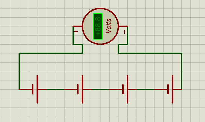
But when using this series configuration there are Key implications you need to know:
- Current remains the same as a single cell. This means that in the above calculation if we used a 25Ah of LiFePO₄ cells in series we would have a total of 51.2V, 25Ah.
- The total energy delivered depends on both the voltage and the combined series string capacity. So the total energy in this case will be 51.2 x 25 = 1,280wh, 1.28kwh.
- Weakest link principle: If one cell in a series string degrades faster or develops higher internal resistance, it limits the performance of the entire string. This makes cell balancing essential for long-term reliability.
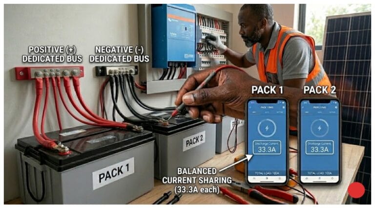
Parallel Connection (Capacity and Current Increase)
- In a parallel connection, all positive terminals are connected together, and all negative terminals are connected together.
- Voltage remains the same as a single cell, but capacity and maximum current output increase:
Cparallel=Ccell×Nparallel
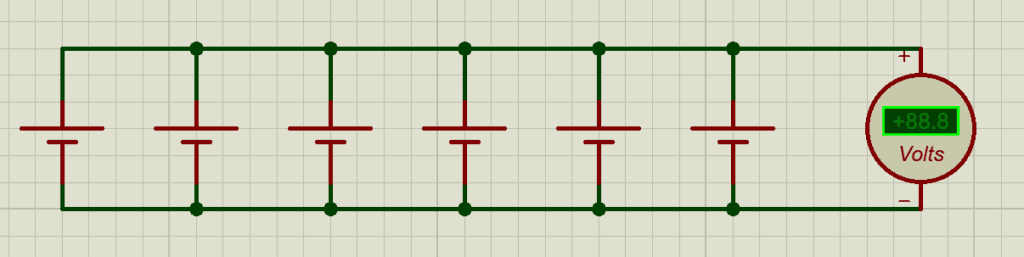
- Example: 16, 25 Ah cells in parallel create a 400 Ah block at the same nominal voltage.
Key implications:
- Parallel groups share current demand, reducing stress on individual cells.
- Properly matched cells are essential; mismatched capacities or internal resistances can cause uneven current sharing, leading to accelerated degradation of weaker cells.
- Total energy delivered will be 1,280wh or 1.28kwh, because if you multiply 400 x 3.2V
so whether in series or parallel connection, Total energy delivered, remains the same.
Combined Series-Parallel Structures
Most practical battery packs use series-parallel combinations:
- Multiple cells in parallel form a parallel group (block) to achieve the required capacity (Ah).
- Multiple parallel groups are connected in series to achieve the required pack voltage (V).
Vpack=Vcell×Nseries,
Cpack=Ccell×Nparallel
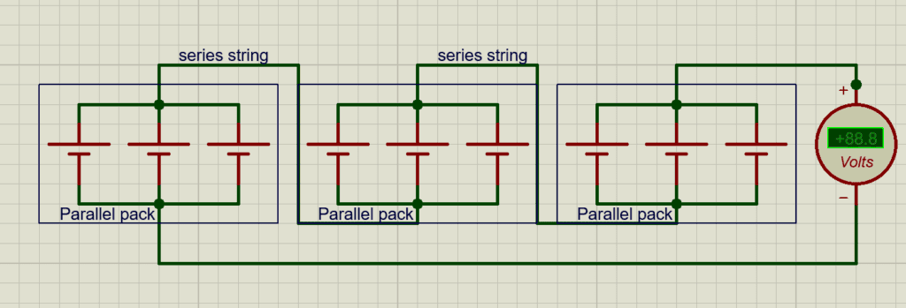
Example:
- A 48 V, 100 Ah LiFePO₄ pack:
- 16 cells in series → 51.2 V nominal
- 16 cells in parallel per series string → 400 Ah total
Key considerations:
- Uniformity in cell capacity, internal resistance, and voltage is critical.
- Series-parallel design directly impacts BMS complexity, wiring, thermal management, and safety.
Cell Grouping Logic Inside Packs
- Cells are often organized into modules for easier manufacturing, monitoring, and replacement.
- Grouping logic considers:
- Voltage and capacity requirements
- Thermal management (heat dissipation across cells)
- Current paths and bus bar thickness
- Ease of BMS monitoring and balancing
- Well-designed packs use consistent grouping and robust interconnections to prevent hotspots, overcurrent conditions, and premature cell failure.
Why This Matters?
The way cells are grouped determines pack performance, reliability, and safety:
- Poorly designed series-parallel layouts can cause uneven aging, voltage imbalance, and thermal stress.
- Proper grouping ensures that voltage and capacity scale predictably, while giving the BMS full control over individual cell monitoring and protection.
series and parallel configurations are the backbone of battery pack architecture, translating individual cell performance into usable system voltage and energy.
Bus Bars and Internal Electrical Interconnections
Once individual cells are arranged in their series and parallel configurations, their electrical connections become the critical pathways that carry current safely and efficiently. The design, material choice, and quality of these interconnections directly influence performance, reliability, and lifespan of a lithium battery pack. We have lots of materials used for the interconnections, which we will be comparing their behaviors and design implications
Copper vs. Aluminum Bus Bars
- Copper Bus Bars:
- High electrical conductivity (~5.8 × 10⁷ S/m), low resistance.
- Excellent for high-current applications and long-term reliability.
- Heavier and more expensive than aluminum.
2. Aluminum Bus Bars:
- Lower conductivity (~3.5 × 10⁷ S/m) than copper.
- Lightweight and cost-effective.
- Often requires larger cross-sectional area to achieve similar resistance to copper.
Implications:
- Bus bar material affects voltage drop, heat generation, and current capacity.
- In high-current solar inverters or EV applications, copper is preferred for critical connections because of its excellent conductivity and low resistance.
Nickel Strips and Weld Points
- Nickel Strips:
- Common in cylindrical and prismatic cells, especially in consumer-grade packs.
- Thin, flexible, and easy to spot-weld, but limited current capacity.
- Often used to connect series strings or parallel groups of cells.
- Weld Points:
- Spot welding or ultrasonic welding ensures a secure, low-resistance connection between strips and cell terminals.
- Poor weld quality increases contact resistance, creating hotspots and potential failure points.
Key consideration:
- Overly thin nickel strips or inconsistent welds can limit current, accelerate degradation, and increase thermal risk.
- High-quality packs use thicker nickel strips, reinforced bus bars, or copper inserts for critical high-current paths.
Contact Resistance and Its Impact
Contact resistance is the small but unavoidable electrical resistance that exists at every connection point inside a battery pack between cell terminals, bus bars, welds, and bolted joints. While it may seem insignificant, its effects become severe under high current conditions.
When contact resistance is low and consistent, current flows evenly, voltage drop is minimal, and heat generation is controlled. This is what you see in well-engineered packs that use thick bus bars, clean mating surfaces, and high-quality welds or torque-controlled bolts.
When contact resistance is high or uneven, several problems emerge:
- Voltage drop under load, causing inverter cutoffs or poor surge performance
- Localized heating, which accelerates cell aging and can damage insulation or welds
- Uneven current sharing, especially in parallel groups, leading to cell imbalance
- Reduced efficiency, as energy is wasted as heat instead of useful power
Maintaining low, uniform contact resistance across all connections is crucial for both efficiency and safety.
Current Distribution Within the Pack
- Proper bus bar design ensures that current is evenly distributed across all cells in a series or parallel group.
- Uneven current flow leads to:
- Overloaded cells in parallel strings
- Localized heating
- Early capacity fade or cell failure
- Engineering strategies:
- Use of thick, low-resistance bus bars
- Symmetrical cell arrangements
- Robust welds or bolted connections for high-current pathways
- Integration with BMS sensing points to monitor voltage drops and detect irregularities
Why This Matters
Bus bars and internal interconnections are not just passive components; they are the veins through which energy flows.
- Substandard materials, thin strips, or poor welds can convert a high-quality cell into a weak, dangerous pack.
- Optimized bus bar design ensures the pack can safely deliver rated power, tolerate surge loads, and maintain consistent aging across cells.
In essence, even the best cells fail if the internal electrical pathways are poorly engineered.
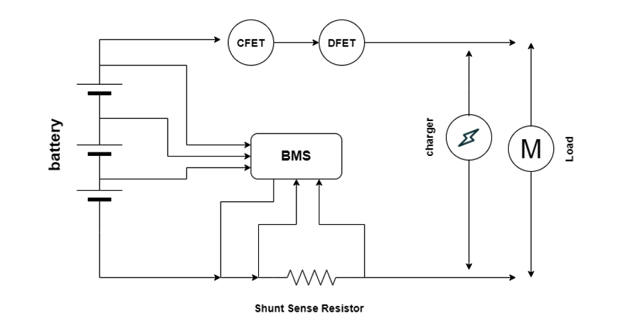
Battery Management System (BMS)
Lithium cells are powerful but unforgiving. They have no inherent awareness of their own limits. The Battery Management System (BMS) exists to enforce those limits in real time. It is not an optional add-on, and it is not merely a safety board it is the control authority that determines whether a battery pack operates as a long-term asset or a short-lived liability.
Also Read: How Smart BMS Balancing Algorithms Protect Lithium Battery Packs
In solar installations, particularly in environments characterized by high ambient temperatures, unstable grid interactions, inverter surge currents, and daily deep cycling, the BMS is often the primary determinant of reliability, not the cells themselves. A pack built with premium cells and a weak BMS will fail. A well-designed BMS is designed to implement these core functions on a lithium battery pack;

1. Cell-Level Voltage Sensing
A competent BMS continuously monitors the voltage of every individual cell or parallel cell group in the series string. This is the foundation of all higher-level protection and control.
Lithium cells do not fail gracefully. A single cell that exceeds its maximum charge voltage experiences electrolyte breakdown and accelerated aging. A single cell that is driven below its minimum discharge voltage suffers irreversible internal damage. In both cases, the overall pack voltage may still appear normal.
This is why pack-level voltage monitoring alone is insufficient. Without accurate, high-resolution cell-level sensing, the BMS is effectively blind to the most dangerous failure modes.
In poorly designed packs, one drifting cell silently limits usable capacity for months before triggering sudden shutdowns or thermal events. In properly designed systems, the BMS detects this deviation early and intervenes long before failure becomes visible.
2. Current Sensing
Current sensing allows the BMS to quantify how hard the battery is being driven at any moment. This is typically achieved using precision shunt resistors or, in higher-end systems, Hall-effect sensors.
Accurate current measurement enables:
- Enforcement of maximum charge and discharge currents
- Detection of short circuits and abnormal surge events
- Coulomb counting, which remains the only reliable method of State of Charge (SOC) estimation due to lithium’s flat voltage curve.
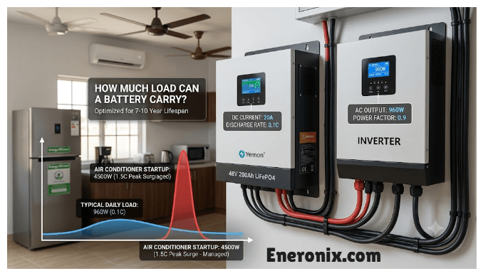
Many battery failures attributed to “weak lithium batteries” are actually BMS current-limit failures. When a 5 kVA inverter attempts to start a borehole pump or compressor, inrush currents can briefly exceed 2 to 3× nominal ratings. A properly engineered BMS allows this surge for a controlled duration. But a cut-corner BMS trips instantly, shutting down the entire system despite healthy cells.
3. Temperature Sensing
Temperature directly influences lithium cell safety, internal resistance, charge acceptance, and aging rate. As a result, temperature sensing is a primary control input, not a secondary alarm.
The BMS uses this data to:
- Reduce charge current (Crate) as temperature rises
- Block charging at low temperatures where lithium plating can occur
- Trigger controlled shutdowns when thermal limits are exceeded
In hot climates, batteries rarely fail due to over-voltage alone. They fail because elevated temperature silently accelerates degradation until internal resistance rises and performance collapses. A BMS that does not actively manage temperature is merely delaying failure.
4. Protection Functions
Protection mechanisms are the BMS’s enforcement tools. They operate continuously and autonomously.
Core protections include:
- Over-voltage and under-voltage protection (cell and pack level)
- Over-current protection for charge and discharge
- Short-circuit protection with ultra-fast response
- Over-temperature and under-temperature protection
These functions are implemented using MOSFET arrays or contactors rated for both continuous current and surge events. The quality of these components and how conservatively they are specified directly affects reliability.
A BMS that trips too easily causes nuisance shutdowns. A BMS that reacts too slowly allows permanent damage. Proper design lies in precise thresholds and intelligent timing.
5. Balancing Circuits
No two cells age identically. Over time, small differences in capacity and internal resistance cause cells in a series string to drift apart. Cell balancing, a crucial BMS function, is implemented in two primary ways:
Passive balancing
dissipates excess energy from higher-voltage cells as heat. It is simple and inexpensive but slow and limited in effectiveness.
Active balancing
transfers energy from stronger cells to weaker ones. It operates across a wider state-of-charge range, improves usable capacity, and significantly extends pack life especially in large or heavily cycled systems.
In practice, many low-cost batteries advertise “balancing” but implement only minimal passive circuits that cannot keep up with real-world imbalance. The result is gradual capacity loss disguised as normal aging.
6. Control and Cutoff Logic
Control and Cutoff Logic, the BMS Decision Engine is a firmware-level control algorithm that converts real-time sensor data into protective actions for the battery pack. It defines the system’s response profile, determining how and when the pack disconnects or limits operation.
Key Technical Components:
1. Multi-Parameter State Machines:
Advanced BMS logic continuously evaluates multiple parameters cell voltage, pack current, temperature, and elapsed time simultaneously rather than as isolated thresholds. The system monitors dynamic rates of change, including dv/dt and dT/dt, to predict and prevent unsafe conditions.
2. Hysteresis and Debouncing:
To prevent rapid oscillations and false triggers, protection logic incorporates hysteresis and debounce mechanisms. For example, a discharge cutoff at 2.5 V per cell may only reset above 3.0 V per cell, and transient events must exceed a defined persistence interval (e.g., overcurrent persisting >500 ms) before triggering protective action.
3. Graceful Degradation vs. Hard Cutoff:
Rather than abrupt shutdowns, modern BMS algorithms implement derating strategies. As cell voltage approaches minimum thresholds, the BMS may command the inverter to linearly reduce discharge power. Similarly, charge currents are tapered as voltages approach maximum limits, reducing stress on cells while maintaining partial operation.
4. Tiered Response Levels:
- Level 1 (Warning): Modulate charge/discharge current to mitigate stress.
- Level 2 (Protection): Disconnect MOSFETs or contactors after a defined delay.
- Level 3 (Latch/Hard Fault): Trigger a non-recoverable fault requiring manual reset or diagnostic intervention.
5. Communication Protocol Handling:
The decision engine integrates with external controllers via CAN bus, RS-485, or UART interfaces, enabling transmission of SOC/SOH data, reception of charge/discharge commands, and execution of controlled shutdown sequences.
6. Cutoff Mechanisms:
- Short-Circuit Protection (SCP): Implemented in hardware using ultra-fast comparators (<200 µs response), bypassing standard software logic.
- Software Cutoffs: Configurable timers govern overload responses (e.g., 5 s at 150 % of rated current, 100 ms at 300 % of rated current).
While basic BMS logic operates as a simple set of if-then conditions, professional-grade BMS decision engines function as adaptive controllers, dynamically managing system stress, optimizing safety, and minimizing operational disruption.
Many lithium batteries that “randomly shut down at night” are not defective. Their BMS is making crude decisions without context, cutting power instead of managing it.
The Engineer’s Note
When two lithium battery packs look identical on the outside, the most meaningful difference is almost always inside the BMS. Sensor accuracy, current-path design, balancing capability, thermal logic, and software decisions determine whether the battery delivers on its rated lifespan or quietly fails years early.
The BMS is not just protecting the battery. It is defining how intelligently that battery participates in the entire power system.
Thermal Monitoring and Heat Management
In a lithium battery, heat is one of the most critical factors affecting lithium battery performance, safety, and lifespan. Proper thermal monitoring and management inside a battery pack prevent degradation, thermal runaway, and efficiency loss. And understanding the sources of heat, sensor placement, and mitigation strategies is essential for any high-quality lithium pack.
Lithium cells produce heat during normal operation due to:
Internal Resistance:
- Every cell has inherent resistance to current flow.
- Higher current (charging or discharging) causes resistive heating (I²R losses).
Electrochemical Reactions:
- During high-rate charging from 2C, intercalation of lithium ions into the anode generates localized heat.
- Fast discharge can also cause uneven temperature rises across cells.
Connection Points:
Bus bars, welds, and nickel strips with high contact resistance can produce hotspots.
Environmental Heat:
Ambient temperature contributes to overall pack temperature, especially in outdoor solar installations or enclosed enclosures.
Heat accelerates capacity fade, increases internal resistance, and, if unchecked, may lead to thermal runaway or cell failure.
Temperature Sensor Placement
Accurate thermal monitoring depends on the strategic placement of temperature sensors throughout the battery system. Sensors are positioned on the surface of individual cells to capture localized temperature variations and identify potential hotspots. Additional sensors are placed at module or pack midpoints to assess overall thermal balance, while sensors near bus bars and other high-current paths where elevated temperatures can indicate increased resistance or developing connection issues.
Commonly used temperature sensors include thermistors, RTDs, and digital temperature probes.
selecting each based on accuracy, response time, and system requirements. The data collected from these sensors is continuously fed into the Battery Management System (BMS), allowing real-time thermal protection, intelligent load management, and automated activation of cooling mechanisms.
Impact of Temperature on Cell Behavior
From my work with lithium-based battery systems, I’ve seen how strongly temperature influences performance, safety, and long-term reliability. At elevated temperatures above roughly 45–50 °C, chemical degradation accelerates, which directly reduces cycle life. Internal resistance increases, leading to voltage sag and higher self-discharge rates, and if safety mechanisms fail, the risk of thermal runaway rises significantly.
Low temperatures present a different set of challenges. Below 0 °C for LiFePO₄ and below 10 °C for NMC chemistries, ion mobility is reduced, increasing internal resistance and limiting power delivery. Charging at low temperatures must be carefully controlled, as aggressive charging can lead to lithium plating. Under extreme cold, discharge capacity is temporarily reduced, even though the cell chemistry itself may remain intact.
Based on these characteristics, I design systems to operate within well-defined thermal windows. For LiFePO₄ cells, the optimal operating range is typically 20 to 45 °C, while NMC and NCA chemistries perform best between 15 to 40 °C. Temperature directly affects efficiency, usable capacity, safety margins, and overall lifespan, which is why precise thermal monitoring and active heat management are non-negotiable in any serious battery design.
This matters because even the most carefully engineered cells and pack architectures will fail prematurely if heat is not properly managed. Intelligent thermal monitoring allows the BMS to balance loads, trigger cooling or heating responses, and prevent localized hotspots before they escalate. Effective heat management ultimately maximizes service life, preserves capacity, and protects the battery pack from catastrophic failure.
In short, thermal monitoring and heat control are just as critical as cell selection itself. Without them, even premium chemistries such as LiFePO₄ can degrade rapidly under high cycle counts or exposure to extreme environmental conditions.
Mechanical Structure and Insulation
Mechanical design is a core determinant of lithium battery pack safety, reliability, and service life. Proper structural integration protects cells from vibration, shock, and mechanical misalignment, while effective insulation ensures electrical isolation and controlled thermal behavior.
Cell holders and compression frames maintain precise cell positioning, preserve inter-cell spacing, and support thermal airflow. Compression is particularly critical for prismatic and pouch cells, where uniform pressure limits swelling during cycling, stabilizes electrical interfaces, and reduces mechanically induced degradation. Insufficient or uneven support increases contact resistance and accelerates premature failure.
Lithium cells are sensitive to mechanical stress. Excessive vibration or impact can result in separator damage, electrode displacement, internal short circuits, and degradation of welds or bus bar interfaces. Vibration mitigation measures including elastomeric dampers, compliant spacers, and shock-isolated mounting are essential in mobile, transportable, and industrial applications.
Electrical insulation prevents short circuits between cells, current-carrying conductors, and conductive enclosure elements. Typical insulating materials include polyimide (Kapton), PET films, silicone-based sheets, and composite separators. In addition to electrical isolation, insulation contributes to thermal uniformity by reducing localized heat concentration.
The enclosure functions as the primary mechanical and environmental protection layer. It maintains structural integrity under mechanical loads, limits ingress of dust and moisture, and incorporates flame-retardant or thermal barrier materials to reduce fault propagation. Proper enclosure design also supports safe installation, handling, and maintenance.
Protection Components
While the Battery Management System makes decisions, protection components execute consequences. These are the physical devices that interrupt current when electronic control fails, reacts too slowly, or encounters conditions beyond its design envelope. In professional battery engineering, no single layer of protection is trusted alone. Fuses, current interrupters, and disconnect devices exist to provide hard, irreversible safety boundaries.
A lithium battery pack without properly engineered protection hardware is not robust it is merely hopeful.
1. Fuses and Current Interrupters
Fuses are the most fundamental protection devices in a battery pack. They are designed to open the circuit when current exceeds a safe threshold for a defined duration.
Common implementations include:
- Cell-level fuses (wire bonds or fusible links)
- Module-level fuses
- Main pack fuses (ANL, NH, or cartridge types)
Unlike a BMS cutoff, a fuse:
- Requires no software
- Requires no sensing logic
- Cannot be overridden
Its purpose is to protect against catastrophic overcurrent events such as internal shorts, bus bar failures, or BMS transistor failures.
High-quality packs often use current interrupter devices (CIDs) or pressure-activated fuses within cells or modules. These devices permanently disconnect a cell if internal pressure rises due to gas generation—an early indicator of thermal runaway.
Low-cost packs often omit cell-level protection entirely, relying on a single external fuse. When one cell fails internally, the rest of the pack continues to dump energy into it—often with destructive results.
2. Short-Circuit Protection
Short-circuit protection must operate on a different timescale than overload protection.
A short circuit can generate:
- Thousands of amps in milliseconds
- Instantaneous heating of conductors
- Explosive failure if not interrupted immediately
Protection is implemented through:
- High-speed fuses with low I²t ratings
- BMS-controlled MOSFETs or contactors
- Physical separation and insulation design
A properly designed system layers protection:
- The BMS detects abnormal current rise and commands shutdown
- If the BMS fails or reacts too slowly, the fuse opens the circuit
In many failed lithium packs, post-mortem analysis shows intact cells but vaporized nickel strips or melted bus bars. The fault was not the cells it was inadequate short-circuit protection that allowed current to rise faster than the interruption system could respond.
3. Emergency Disconnects
In larger battery systems particularly those used in residential, commercial, or industrial installations manual or automatic emergency disconnects are increasingly required.
These may include:
- Manual service disconnects
- High-voltage contactors
- Pyrotechnic disconnects (in EV-derived systems)
Their functions are to:
- Allow safe servicing and transport
- Enable emergency shutdown during fire or fault conditions
- Isolate the battery from the inverter or DC bus
In grid-tied or hybrid solar systems, emergency disconnects also protect:
- Installers during maintenance
- Fire responders during incidents
Small consumer batteries often omit these features due to cost and space constraints. However, as system power increases, the absence of a disconnect becomes a serious safety and compliance issue.
Electronic protection can fail silently. Software can hang. Sensors can drift. MOSFETs can short internally. When that happens, only physical protection remains.
Well-engineered battery packs assume failure will occur and design for it. Poorly engineered packs assume perfection and are surprised when reality intervenes.
Protection components do not improve performance, increase capacity, or make marketing claims. They exist for one reason only: to prevent a bad day from becoming a disaster.
Signal, Data, and Communication Paths
While power paths move energy, signal and communication paths move intelligence. These low-voltage circuits allow the Battery Management System (BMS) to sense, decide, and coordinate both internal protection and external system behavior. In modern lithium battery packs especially those integrated into solar, inverter, and energy management systems communication integrity is as important as electrical robustness.
Many battery failures blamed on “bad cells” or “faulty BMS” are, in reality, failures of signal integrity, noise immunity, or poor internal wiring design.
Internal Wiring Harnesses
Internal wiring harnesses carry low-voltage signals from cells, temperature sensors, current sensors, and balancing circuits to the BMS control board.
Key design requirements include:
- Consistent conductor length and routing to minimize measurement offset
- High-quality insulation rated for pack voltage and temperature
- Mechanical strain relief to prevent fatigue from vibration or thermal expansion
- Clear separation from high-current paths to reduce electromagnetic interference (EMI)
In well-engineered packs, signal wires are:
- Twisted or shielded where necessary
- Routed orthogonally to power conductors
- Secured to prevent movement
In low-cost designs, signal wiring is often:
- Loosely routed
- Unshielded
- Placed directly alongside bus bars
This leads to noisy voltage readings, false temperature alarms, intermittent shutdowns, and balancing errors—issues that appear “random” but are rooted in poor internal wiring discipline.
Communication Between BMS and Cells
Within the pack, the BMS communicates with:
- Cell voltage sense points
- Temperature sensors
- Balancing circuits
- Secondary monitoring boards (in modular designs)
This communication is typically:
- Analog (voltage sensing lines)
- Digital (SPI, I²C, proprietary daisy-chain protocols)
Accuracy and stability are critical. A few millivolts of noise on a cell sense line can cause:
- Premature over-voltage cutoffs
- False imbalance detection
- Ineffective balancing
In some failed packs, cells were healthy but one noisy sense line caused the BMS to believe a cell was over-charged. The result was repeated shutdowns, misdiagnosed as “battery failure,” when the true issue was signal interference.
Professional designs include:
- Input filtering
- Reference voltage stabilization
- Fault detection for open or shorted sense wires
External Communication Interfaces (CAN, RS485, UART)
External communication allows the battery to interact with the wider energy system—most importantly the inverter, charge controller, or monitoring platform.
CAN (Controller Area Network)
- Differential, noise-resistant
- Real-time, deterministic communication
- Standard in EVs and high-end energy storage
Used to exchange:
- SOC, SOH
- Charge and discharge limits
- Alarms and fault codes
A battery with proper CAN integration can actively control the inverter, not just react to it.
RS485
- Differential, robust over long distances
- Common in industrial and solar equipment
- Often used with Modbus protocols
RS485 enables:
- Monitoring and configuration
- Multi-device communication on a single bus
It is simpler than CAN but lacks the same real-time control depth.
UART
- Simple point-to-point serial communication
- Low cost, limited noise immunity
- Common in budget batteries and DIY systems
UART works well internally or over short distances but is easily disrupted by electrical noise if poorly implemented.
Why Communication Paths Matter in Practice
A lithium battery that cannot communicate effectively is forced into defensive operation:
- Fixed current limits
- Conservative voltage thresholds
- Hard cutoffs instead of coordinated derating
By contrast, a battery with robust communication:
- Negotiates charge rates with the inverter
- Prevents over-stress before protection triggers
- Logs faults accurately for diagnostics
- Integrates cleanly into energy management systems\
Many inverter-battery incompatibility issues are not chemistry problems they are communication mismatches. When communication fails, systems fall back to unsafe assumptions or overly conservative defaults.
Signal and communication paths are not just “small wires.” As people call it, they are the control infrastructure that makes modern lithium batteries viable in complex power systems. Poor signal design undermines even the best cells and BMS logic. Good communication design turns a battery from a passive energy source into an active, cooperative system component.
Failure Points Inside a Lithium Battery Pack
Lithium battery failures rarely occur without warning. In most cases, they are the result of predictable internal weaknesses that develop over time due to design shortcuts, component mismatches, or poor integration. Understanding these failure points is essential not only for diagnostics, but for evaluating battery quality long before failure occurs.
What makes lithium battery failures particularly deceptive is that many packs continue to operate sometimes for months while internal damage quietly accumulates.
1. Cell Imbalance
Cell imbalance occurs when cells within a series string drift to different states of charge due to variations in capacity, internal resistance, temperature exposure, or aging rate.
Once imbalance begins:
- The highest cell reaches over-voltage first during charging
- The lowest cell hits under-voltage first during discharge
- The usable capacity of the entire pack collapses to that of the weakest cell
If balancing circuits are weak or ineffective, the BMS is forced into repeated protection events, often misinterpreted as “random shutdowns.”
Many “dead” lithium batteries still contain 80–90% healthy cells. But one chronically imbalanced cell silently dictates the behavior of the entire pack.
2. Connector Overheating
Connector and interconnection failures are among the most common—and most underestimated failure points.
Causes include:
- Undersized bus bars or nickel strips
- Poor weld quality
- Loose bolted joints
- Corrosion or oxidation
Even milliohms of extra resistance can generate significant heat under high current:
P=I2R
This localized heating:
- Accelerates insulation degradation
- Warps terminals
- Increases resistance further (a positive feedback loop)
- Can trigger thermal sensors or melt conductors
In solar systems, connector overheating is frequently mistaken for “cell overheating,” leading to incorrect root-cause diagnosis.
BMS Component Failure
The BMS itself is a collection of electronic components operating in a harsh electrical and thermal environment.
Common failure points include:
- MOSFETs undersized for inverter surge currents
- Shunt resistors overheating or drifting
- Voltage sense ICs damaged by transients
- Poor PCB thermal design
When BMS components fail, they often fail silently:
- Protection thresholds drift
- Current readings become inaccurate
- Balancing stops working
- Communication becomes intermittent
The pack may continue operating until a real fault occurs and the BMS can no longer respond correctly.
Thermal Sensor Faults
Temperature sensors are critical for preventing thermal stress, but they are also vulnerable.
Typical issues include:
- Sensors detaching from cell surfaces
- Broken wires due to vibration
- Sensor drift due to prolonged heat exposure
- Poor placement that fails to capture hot spots
A faulty sensor can cause:
- False overheating shutdowns
- Dangerous under-reporting of actual cell temperature
A pack that appears “cool” in software may be experiencing localized heating at a terminal or bus bar that the BMS never sees.
Insulation Breakdown
Insulation inside a battery pack prevents unintended current paths between:
- Cells
- Bus bars
- Enclosures
Breakdown occurs due to:
- Heat aging
- Mechanical abrasion
- Chemical exposure from electrolyte vapors
- Poor material selection
Once insulation weakens:
- Leakage currents increase
- Local heating intensifies
- The risk of internal short circuits rises sharply
Unlike electronic faults, insulation failures often escalate rapidly once they reach a critical threshold.
The Engineering Truth
Lithium battery packs do not fail randomly. They fail at the intersection of electrical stress, thermal stress, and mechanical weakness. Every failure point discussed here can be traced back to a design decision what was sized, where it was placed, and how much margin was allowed.
Well-engineered packs assume that components will age, connections will loosen slightly, and temperatures will fluctuate. Poorly engineered packs assume ideal conditions and are shocked when reality intervenes.
Conclusion
A lithium battery pack is not defined by its chemistry alone, nor by its advertised capacity or cycle life. Its real performance, safety, and longevity are determined by the internal architecture the cells, electrical interconnections, thermal pathways, protection mechanisms, and control intelligence working together as a system.
Throughout this work, we have broken the battery pack down to its fundamental building blocks: the internal structure of individual cells, electrical parameters, series and parallel configurations, current paths, bus bars, thermal management, mechanical support, protection components, communication systems, and failure modes. What emerges is a clear engineering reality: every internal decision carry consequence.
High-quality cells can be rendered unsafe by poor interconnections. A robust enclosure cannot compensate for weak thermal monitoring. A powerful inverter-facing pack becomes unreliable if its BMS logic is crude or its sensors inaccurate. Conversely, disciplined engineering proper current handling, effective balancing, conservative protection thresholds, and thoughtful thermal design can extract long, predictable service life even from modest cell chemistries.
Perhaps the most important takeaway is this: lithium battery failures are rarely sudden or mysterious. They are almost always the result of internal stresses that were allowed to accumulate cell imbalance, localized heating, component derating, insulation degradation, or sensing blind spots. These are not accidents; they are outcomes.
For system designers, installers, and technically informed users, understanding what happens inside the pack transforms battery selection from brand comparison into engineering evaluation. It shifts the question from “How many kilowatt-hours?” to “How well is this energy controlled, protected, and managed over time?”
In energy storage especially in demanding environments such as solar and hybrid power systems the battery pack is not just an energy container. It is an electromechanical system whose reliability is earned through internal discipline, not external claims. Knowing what is inside is the difference between short-term performance and long-term trust.

I am Engr. Ubokobong Ekpenyong, a solar specialist and lithium battery systems engineer with over five years of hands-on experience designing, assembling, and commissioning off-grid solar and energy storage systems. My work focuses on lithium battery pack architecture, BMS configuration, and system reliability in off-grid and high-demand environments.